 Back
BackCurrent, Resistance, and Electromotive Force: Study Notes
Study Guide - Smart Notes
 Tailored notes based on your materials, expanded with key definitions, examples, and context.
Current, Resistance, and Electromotive Force
Introduction to Electric Circuits
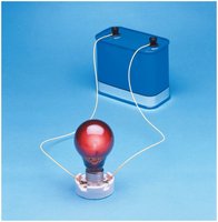
Electric circuits are fundamental to modern technology, enabling the operation of devices from flashlights to computers. In a circuit, charges move through conductors, transferring energy to components such as light bulbs. The current entering and leaving a device remains constant, but the energy carried by the charges decreases as they pass through resistive elements. 
Electric Current
Electric current is defined as the motion of charge from one region to another. It can be carried by positive or negative charge carriers, depending on the material.
Definition: Current (I) is the rate at which charge flows through a conductor, measured in amperes (A).
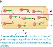
Conventional Current: By convention, current is considered as the flow of positive charges, regardless of the actual charge carriers.
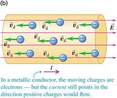
Direction: In metallic conductors, electrons move, but the current direction is defined as the direction positive charges would flow.
Charge Carriers in Conductors
Conductors may contain multiple types of moving charged particles. For example, in ionic solutions, both positive and negative ions contribute to the total current.
Total Current: The total current is the sum of the currents due to each type of charge carrier.
Example: In a sodium chloride solution, sodium ions (Na+) and chloride ions (Cl-) both carry current.

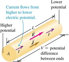
Current Density
Current density is a vector quantity that describes the amount of current flowing per unit area, including the direction of the drift velocity.
Formula: where is the number density of charge carriers, is the charge, and is the drift velocity.
Direction: Current density is always in the direction of the electric field.
Resistivity and Conductivity
Resistivity () is a material property that quantifies how strongly a material opposes the flow of electric current. Conductivity () is its reciprocal.
Resistivity Formula: where is the electric field and is the current density.
Conductivity Formula:
Resistivity in Circuit Boards
Circuit boards use materials with high resistivity to prevent unwanted current flow between conducting traces. 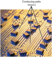
Resistivity and Temperature
The resistivity of materials changes with temperature.
Metals: Resistivity increases with temperature due to increased atomic vibrations.
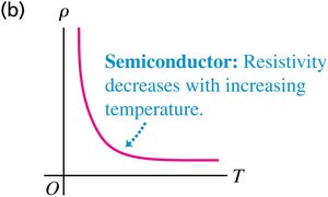
Semiconductors: Resistivity decreases with temperature as more charge carriers become available.
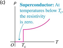
Superconductors: Below a critical temperature (), resistivity drops to zero.
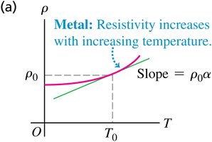
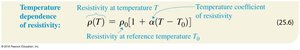
Equation: where is the resistivity at reference temperature , and is the temperature coefficient.
Resistance and Ohm’s Law
Resistance () is the opposition to current flow in a conductor. Ohm’s law relates voltage (), current (), and resistance:
Ohm’s Law:
Resistance Formula:
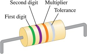
Resistor Identification
Resistors are color-coded for easy identification of their resistance values and tolerances. 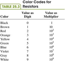
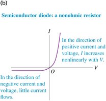
Ohmic and Nonohmic Resistors
Ohmic Resistors: Obey Ohm’s law; current is proportional to voltage.
Nonohmic Resistors: Do not obey Ohm’s law; current and voltage are not directly proportional.
Electromotive Force (emf) and Circuits
Electromotive force (emf) is the energy-per-unit-charge supplied by a source to move charges through a circuit.
Definition: Emf is not a force, but a potential difference (measured in volts).
Example: A battery with emf of 1.5 V does 1.5 J of work per coulomb of charge.

Internal Resistance
Real sources of emf have internal resistance (), which reduces the terminal voltage when current flows.
Terminal Voltage Formula:

Circuit Diagram Symbols
Circuit diagrams use standardized symbols to represent components. 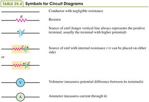
Potential Changes in Circuits
As current moves through a circuit, potential rises across sources of emf and drops across resistors. Completing the loop returns the potential to its starting value. 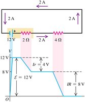
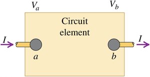
Energy and Power in Electric Circuits
The power () delivered to or extracted from a circuit element is the product of the potential difference and the current.
Power Formula:

Power in Circuits with Internal Resistance
The emf source converts energy at a rate , and its internal resistance dissipates energy at a rate . The difference is the power output. 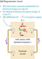
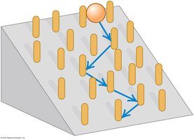
Metallic Conduction
In metallic conductors, electrons move freely through the crystal lattice, colliding with stationary positive ions. Their motion is analogous to a ball rolling down an inclined plane and bouncing off obstacles. 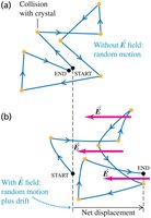
Summary Table: Color Codes for Resistors
Color | Value as Digit | Value as Multiplier |
|---|---|---|
Black | 0 | 1 |
Brown | 1 | 10 |
Red | 2 | 102 |
Orange | 3 | 103 |
Yellow | 4 | 104 |
Green | 5 | 105 |
Blue | 6 | 106 |
Violet | 7 | 107 |
Gray | 8 | 108 |
White | 9 | 109 |
Summary Table: Symbols for Circuit Diagrams
Symbol | Description |
|---|---|
R | Resistor |
\mathcal{E} | Source of emf |
\mathcal{E} with r | Source of emf with internal resistance |
V | Voltmeter |
A | Ammeter |
