 Back
BackDC Circuit Analysis: Source Conversions, Mesh & Nodal Analysis, Bridge Networks, and Y-Δ Conversions
Study Guide - Smart Notes
 Tailored notes based on your materials, expanded with key definitions, examples, and context.
8.2 Current Sources
Duality of Voltage and Current Sources
Voltage sources and current sources exhibit a dual relationship in circuit analysis. The behavior of one can often be translated to the other, especially in terms of how they interact with a network.
Voltage Source: Maintains a fixed voltage across its terminals, regardless of the current drawn (ideal case).
Current Source: Maintains a fixed current through its terminals, regardless of the voltage across it (ideal case).
Duality Principle: What is true for voltage in a voltage source is true for current in a current source, and vice versa.
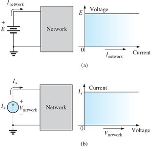
Current Source Characteristics
A current source determines the direction and magnitude of current in its branch. The voltage across a current source is set by the network it is connected to.
Ideal Current Source: Has no internal resistance; delivers constant current regardless of load.
Practical Current Source: Includes internal resistance, affecting performance.
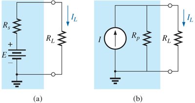
Source Conversion
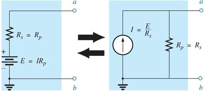
Voltage sources with series resistance can be converted to equivalent current sources with parallel resistance, and vice versa. This is useful for simplifying circuit analysis.
Conversion Equations:
From voltage to current source:
From current to voltage source:
External Terminal Equivalence: The equivalence holds only at the external terminals of the sources.
Combining Current Sources
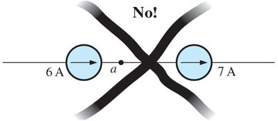
Multiple current sources in parallel can be replaced by a single current source whose value is the algebraic sum of the individual sources, considering their directions. Current sources cannot be placed in series if their values differ, as this violates Kirchhoff’s Current Law (KCL).
Parallel Combination: (direction matters)
Series Restriction: Different-valued current sources cannot be placed in series.
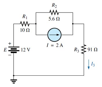
Source Conversion Example
Problems often require converting a current source to a voltage source, combining series voltage sources, and calculating current through a resistor.
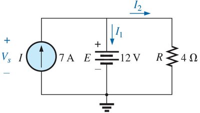
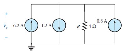
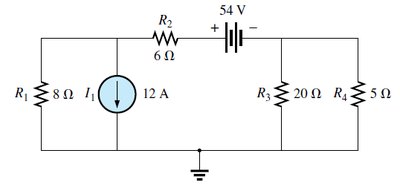
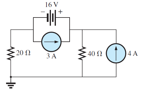
Parallel Current Source Example
Problems may involve replacing multiple parallel current sources with a single equivalent source and finding the source voltage.
8.4 Mesh Analysis (General Approach)
Mesh Currents and Windows
Mesh analysis is a systematic method for solving circuit networks using loop currents. The number of mesh currents equals the number of independent loops (windows) in the circuit.
Mesh/Loop Currents: Currents defined for each independent loop.
Application: Used to determine current through each resistor and voltage at specific points.
Mesh Equations and Determinants
Mesh equations are written for each loop using Kirchhoff’s Voltage Law (KVL). Determinants (matrix methods) can be used to solve for mesh currents.
Supermesh Approach
When a current source lies between two meshes, a supermesh is formed by combining the two meshes and excluding the current source from the KVL equation.
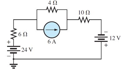
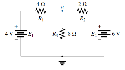
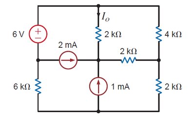
Mesh Analysis Quiz Example
Mesh analysis can be used to determine specific currents in a network.
8.6 Nodal Analysis (General Approach)
Nodal Voltage Calculation
Nodal analysis uses Kirchhoff’s Current Law (KCL) to determine voltages at nodes. The number of unknown node voltages is one less than the total number of nodes.
Nodal Equations: Written for each node except the reference (ground) node.
Determinant Solution: Matrix methods can be used to solve for node voltages.
Supernode Approach
When a voltage source connects two non-reference nodes, a supernode is formed. The supernode equation combines the two nodes and includes the voltage source constraint.
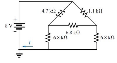
8.8 Bridge Networks
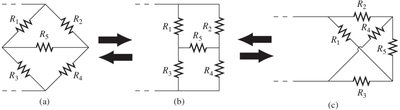
Bridge Network Configuration
Bridge networks are widely used in measurement and instrumentation. A bridge is balanced when the ratio of resistances in one branch equals the ratio in the other branch, resulting in zero current or voltage across the bridge.
Balance Condition:
Applications: Wheatstone bridge, strain gauges, etc.
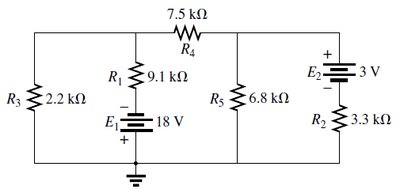
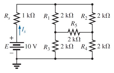
Bridge Network Example
Problems may require determining the current through a source resistor in a bridge network.
8.9 Y-Δ (T-π) and Δ-Y (π-T) Conversions
Wye (Y) and Delta (Δ) Configurations
Wye (Y) and Delta (Δ) configurations are common in circuit analysis, especially for simplifying complex resistor networks. They are also referred to as Tee (T) and Pi (π) configurations.

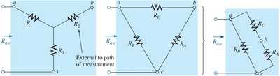
Δ to Y Conversion
To convert a Delta (Δ) network to a Wye (Y) network, use the following formulas:
Each resistor in the Y is equal to the product of the two closest Δ resistors divided by the sum of all Δ resistors. If all resistors are equal:
Y to Δ Conversion
To convert a Wye (Y) network to a Delta (Δ) network, use the following formulas:
Each Δ resistor is the sum of all possible products of Y resistors divided by the Y resistor farthest from the Δ resistor. If all resistors are equal:
Y-Δ Conversion Example
Problems may require finding the current in a network after performing Y-Δ or Δ-Y conversions.
References
R. Boylestad and B. Olivari, Introductory Circuit Analysis, Pearson 14th Edition, 2023.
