Back
BackDC Circuits: Batteries, Resistors, and Circuit Analysis
Study Guide - Smart Notes
 Tailored notes based on your materials, expanded with key definitions, examples, and context.
DC Circuits and Circuit Elements
Basic Circuit Components
DC circuits are composed of batteries (voltage sources), resistors, and connecting wires. Understanding how these elements interact is fundamental to analyzing electrical circuits.
Batteries: Provide a constant voltage (electromotive force, EMF) to drive current through the circuit.
Resistors: Impede the flow of electric current, converting electrical energy into heat.
Ammeters and Voltmeters: Ammeters measure current and are connected in series; voltmeters measure voltage and are connected in parallel.
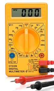
Measurement Tools
Digital multimeters are used to measure voltage, current, and resistance in circuits. Proper use of these instruments is essential for accurate circuit analysis.
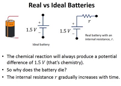
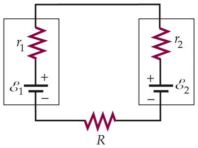
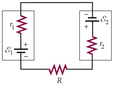
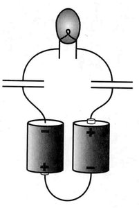
Real vs. Ideal Batteries
Battery Models
Batteries are modeled as either ideal or real. An ideal battery maintains a constant voltage regardless of the current drawn, while a real battery includes internal resistance, which affects its performance over time.
Ideal Battery: No internal resistance; voltage remains constant.
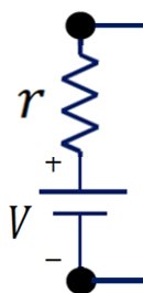
Real Battery: Has internal resistance r; voltage decreases as current increases.
Internal Resistance: Increases with time due to chemical changes, causing the battery to 'die'.
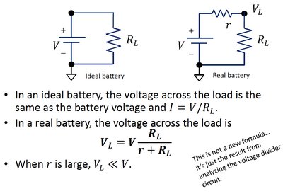
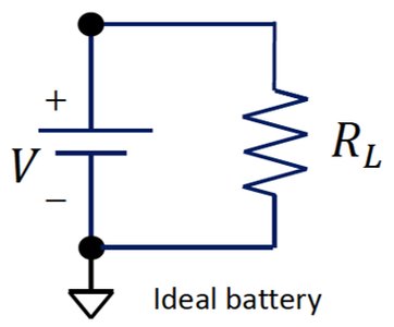
Voltage Across the Load
The voltage across a load resistor R_L differs between ideal and real batteries. In real batteries, the internal resistance reduces the voltage available to the load.
For an ideal battery:
For a real battery:
When r is large,
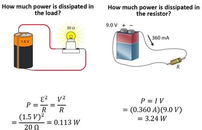
Power Dissipation in Circuits
Calculating Power
Power dissipated in a resistor or load is calculated using the voltage and current. The formulas are:
for a load connected to a battery
for a resistor
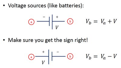
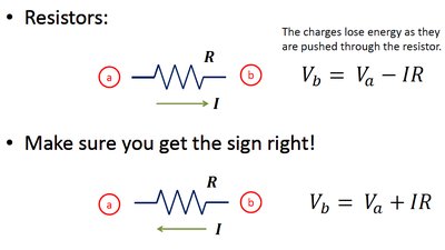
Voltage and Current Relationships
Voltage Sources
When analyzing circuits, it is important to correctly assign voltage differences across batteries and resistors, considering the direction of current and the polarity of the devices.
For a battery: (from negative to positive terminal)
For a battery: (from positive to negative terminal)

Resistors
For a resistor: (current flows from a to b)
For a resistor: (current flows from b to a)
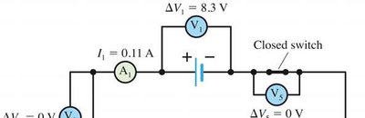
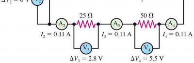
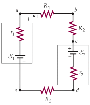
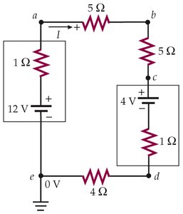
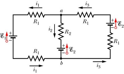
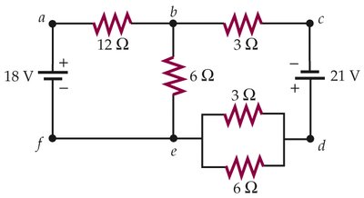
Multi-Loop Circuits and Kirchhoff's Rules
Kirchhoff's Junction and Loop Rules
Kirchhoff's rules are essential for analyzing complex circuits with multiple loops and branches.
Junction Rule: The sum of currents entering a junction equals the sum leaving it (conservation of charge).
Loop Rule: The sum of potential differences around any closed loop is zero (conservation of energy).
Example Circuits
Multi-loop circuits often include batteries with internal resistance and multiple resistors. Applying Kirchhoff's rules allows for the calculation of unknown currents and voltages.
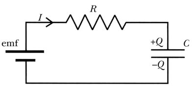
RC Circuits: Charging and Discharging
RC Circuit Structure
An RC circuit consists of a resistor (R) and a capacitor (C) connected in series with a voltage source (emf). The charging and discharging of the capacitor follow exponential laws.
Current and Charge in RC Circuits
Current during charging: , where
Charge on capacitor:
RC is the time constant; after time , current drops by a factor of .

Summary of RC Circuit Behavior
At , and
As , and
The time constant determines how quickly the circuit reaches equilibrium.