 Back
Chapter 19: DC Circuits: Series and Parallel Circuits, Kirchhoff’s Rules, and RC Circuits
Study Guide - Smart Notes
 Tailored notes based on your materials, expanded with key definitions, examples, and context.
DC Circuits
Electromotive Force (EMF) and Terminal Voltage
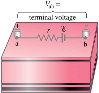
In direct current (DC) circuits, a source of electromotive force (emf) such as a battery provides the energy needed to move charges through the circuit. The terminal voltage is the actual voltage measured across the terminals of the battery, which is less than the emf due to the battery's internal resistance.
EMF (\(\mathcal{E}\)): The maximum potential difference a battery can provide when no current is flowing.
Terminal Voltage (V): The voltage available to the external circuit, given by \(V = \mathcal{E} - Ir\), where \(r\) is the internal resistance and \(I\) is the current.
Unit of Resistance: Ohm (\(\Omega\)), where \(1\,\Omega = 1\,\mathrm{V/A}\).
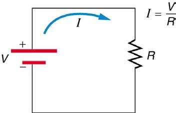
Ohm's Law relates the current (I), voltage (V), and resistance (R) in a circuit:
Resistors in Series and Parallel
Resistors in Series
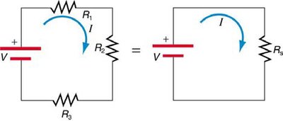
When resistors are connected in series, the same current flows through each resistor, but the voltage divides among them. The total or equivalent resistance is the sum of the individual resistances.
Current: Same through all resistors: \(I = I_1 = I_2 = I_3\)
Voltage: Total voltage is the sum of individual voltage drops: \(V = V_1 + V_2 + V_3\)
Equivalent Resistance: \(R_s = R_1 + R_2 + R_3 + \cdots\)
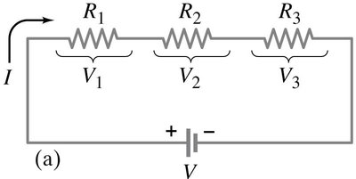
Example: For \(R_1 = 10\,\Omega\), \(R_2 = 5\,\Omega\), \(R_3 = 10\,\Omega\), and \(V = 50\,\mathrm{V}\):
\(R_s = 10 + 5 + 10 = 25\,\Omega\)
\(I = \frac{50\,\mathrm{V}}{25\,\Omega} = 2\,\mathrm{A}\)
\(V_1 = IR_1 = 2 \times 10 = 20\,\mathrm{V}\)
\(V_2 = IR_2 = 2 \times 5 = 10\,\mathrm{V}\)
\(V_3 = IR_3 = 2 \times 10 = 20\,\mathrm{V}\)
Resistors in Parallel
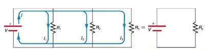
When resistors are connected in parallel, the voltage across each resistor is the same, but the current divides among the branches. The reciprocal of the equivalent resistance is the sum of the reciprocals of the individual resistances.
Voltage: Same across all resistors: \(V = V_1 = V_2 = V_3\)
Current: Total current is the sum of branch currents: \(I = I_1 + I_2 + I_3\)
Equivalent Resistance:
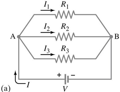
Example: For \(R_1 = 2\,\Omega\), \(R_2 = 100\,\Omega\), \(R_3 = 20\,\Omega\):
(smallest possible resistance)
Series-Parallel Circuits
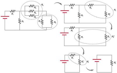
Many practical circuits are combinations of series and parallel connections. To analyze these, reduce the circuit step-by-step by replacing series and parallel groups with their equivalent resistances.
Kirchhoff’s Rules
Junction Rule (First Rule)
The sum of currents entering a junction equals the sum of currents leaving the junction. This is a consequence of the conservation of charge.
Loop Rule (Second Rule)
The sum of the potential differences around any closed loop in a circuit must be zero. This is a consequence of the conservation of energy.
around a closed loop
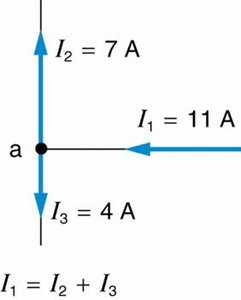
Example: For a single loop with emf \(\mathcal{E}\), internal resistance \(r\), and two resistors \(R_1\) and \(R_2\):
Internal Resistance and Power in Batteries
Internal Resistance
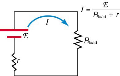
Real batteries have internal resistance, which reduces the terminal voltage and the power delivered to the external circuit.
Terminal Voltage:
Current:
Power delivered to load:
Power lost in battery:
RC Circuits (Resistor and Capacitor in Series)
Charging and Discharging a Capacitor
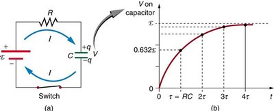
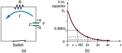
An RC circuit consists of a resistor and a capacitor in series. The voltage and current in the circuit change with time as the capacitor charges or discharges.
Time Constant: (characteristic time for charging/discharging)
Charging:
Discharging:
At , (charging), (discharging)
Applications: RC circuits are used for timing devices, such as camera flashes and windshield wipers.
Summary Table: Series vs. Parallel Resistors
Property | Series | Parallel |
|---|---|---|
Current | Same through all resistors | Divides among branches |
Voltage | Divides among resistors | Same across all resistors |
Equivalent Resistance |
Measurement Devices
Ammeter: Measures current; connected in series with the circuit element.
Voltmeter: Measures voltage; connected in parallel with the circuit element.
Electric Hazards
To avoid electric shocks, never allow your body to become part of a complete circuit. Even small currents can be dangerous.
