 Back
BackDirect-Current Circuits: Series and Parallel Circuits, Kirchhoff’s Rules, RC Circuits, and Electrical Measurement
Study Guide - Smart Notes
 Tailored notes based on your materials, expanded with key definitions, examples, and context.
Direct-Current Circuits
Introduction to Direct-Current Circuits
Direct-current (DC) circuits are fundamental in physics and engineering, describing the flow of electric charge in a single direction through circuit elements such as resistors, capacitors, and batteries. This chapter covers the analysis of circuits with resistors in series and parallel, the application of Kirchhoff’s rules, the behavior of RC circuits, and the use of electrical measuring instruments.
Resistors in Series and Parallel
Resistors in Series
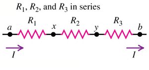
When resistors are connected end-to-end so that the same current flows through each, they are said to be in series. The total or equivalent resistance is the sum of the individual resistances:
Definition: Series connection means the current is identical through all resistors.
Formula:
Key Point: The total voltage across the series combination is the sum of the voltages across each resistor.
Example: Three resistors of 2 Ω, 3 Ω, and 5 Ω in series have .
Resistors in Parallel
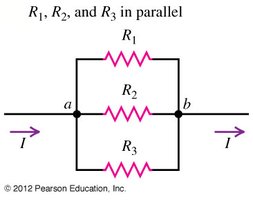
Resistors are in parallel if they are connected so that the potential difference across each is the same. The total or equivalent resistance is found by the reciprocal sum:
Definition: Parallel connection means the voltage across each resistor is identical.
Formula:
Key Point: The total current is the sum of the currents through each resistor.
Example: For three resistors of 2 Ω, 3 Ω, and 6 Ω in parallel: .
Series-Parallel Combinations
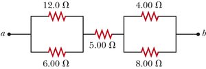
Many practical circuits contain both series and parallel resistor combinations. To analyze these, reduce the circuit stepwise by replacing series or parallel groups with their equivalent resistance.
Key Point: Simplify complex circuits by reducing them to simpler series or parallel parts.
Example: See the circuit below for a combination of series and parallel resistors.
Power in Resistors
The power dissipated by a resistor is given by:
Formula:
Application: Used to determine the brightness of bulbs or the energy consumed by devices.
Conceptual Questions on Series and Parallel Circuits
Which arrangement has smaller equivalent resistance? Parallel arrangements always have a smaller equivalent resistance than series arrangements for the same resistors.
Voltage drop in parallel: All resistors in parallel have the same voltage drop.
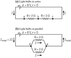
Brightness of bulbs: In parallel, the bulb with the highest power rating glows brightest; in series, the bulb with the highest resistance dissipates the most power.
Kirchhoff’s Rules
Introduction to Kirchhoff’s Rules
For complex circuits that cannot be simplified into series or parallel combinations, Kirchhoff’s rules provide a systematic method for analysis. These rules are based on the conservation of charge and energy.
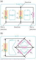
Junction Rule (Current Law): The sum of currents entering a junction equals the sum leaving it ().
Loop Rule (Voltage Law): The sum of potential differences around any closed loop is zero ().
Sign Conventions for Kirchhoff’s Rules
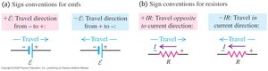
When applying the loop rule, use the following sign conventions:
For EMF (batteries): Positive when moving from negative to positive terminal, negative otherwise.
For Resistors: Negative when moving in the direction of current, positive otherwise.
Reducing Unknowns in Multiloop Circuits
Apply the junction rule to reduce the number of unknown currents in a circuit, making it easier to solve the system of equations generated by the loop rule.
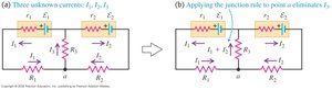
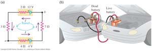
Example: Applying Kirchhoff’s Rules
Consider a circuit with multiple loops and batteries. Assign current directions, write equations for each loop and junction, and solve for unknowns. A negative current indicates the actual direction is opposite to the assumed direction.
RC Circuits (Resistor-Capacitor Circuits)
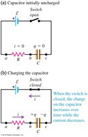
Charging a Capacitor
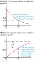
When a capacitor is charged through a resistor, the charge and current change exponentially with time. The time constant characterizes how quickly the capacitor charges.
Charge on capacitor:
Current in circuit:
Time constant: (time to reach ~63% of final charge)
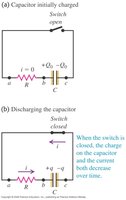
Discharging a Capacitor
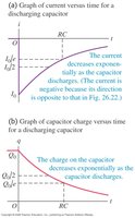
When a charged capacitor is discharged through a resistor, both the charge and current decrease exponentially:
Charge on capacitor:
Current in circuit:
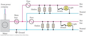
Power Distribution and Household Wiring
Power Distribution Systems
Electric power is distributed from power plants to homes through a network of wires, fuses, and switches. Safety devices such as fuses and circuit breakers protect against overloads.
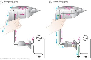
Three-Prong Plugs and Electrical Safety
Three-prong plugs provide an additional ground connection, reducing the risk of electric shock by offering a safe path for stray currents.
Electrical Measuring Instruments
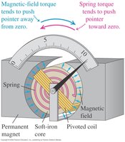
D’Arsonval Galvanometer
A d’Arsonval galvanometer is a sensitive instrument for measuring small currents. It operates on the principle of a coil suspended in a magnetic field, which deflects in proportion to the current.
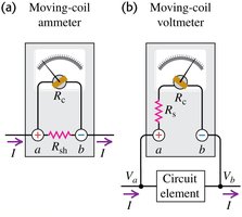
Ammeters and Voltmeters
An ammeter measures current and is connected in series with the circuit element. A voltmeter measures potential difference and is connected in parallel. Both are based on the galvanometer but modified for their specific functions.
Ammeter: Low resistance, measures current through it.
Voltmeter: High resistance, measures voltage across two points.
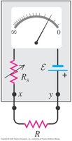
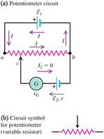
Ohmmeters and Potentiometers
An ohmmeter measures resistance by passing a known current through the resistor and measuring the voltage. A potentiometer measures emf without drawing current from the source, providing accurate voltage measurements.
Summary Table: Series vs. Parallel Resistors
Property | Series | Parallel |
|---|---|---|
Current | Same through all resistors | Divided among branches |
Voltage | Divided among resistors | Same across all resistors |
Equivalent Resistance |
Key Equations
Ohm’s Law:
Power:
Series Resistance:
Parallel Resistance:
Kirchhoff’s Junction Rule:
Kirchhoff’s Loop Rule:
RC Circuit (Charging):
RC Circuit (Discharging):
Additional info: This guide expands on the provided slides and problems with academic context, definitions, and examples to ensure a comprehensive, self-contained study resource for college-level physics students.
