 Back
BackDirect-Current Circuits: Series & Parallel Resistors, Kirchhoff’s Rules, and R-C Circuits
Study Guide - Smart Notes
 Tailored notes based on your materials, expanded with key definitions, examples, and context.
Direct-Current Circuits
Resistors in Series and Parallel
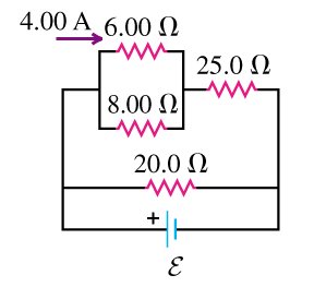
Resistors are fundamental components in electric circuits, and their arrangement affects the total resistance and current distribution in the circuit.
Series Connection: The same current flows through each resistor. The total (equivalent) resistance is the sum of individual resistances.
Parallel Connection: The voltage across each resistor is the same. The reciprocal of the total resistance is the sum of the reciprocals of individual resistances.
Example Calculation: For two resistors, 6 Ω and 3 Ω, in parallel: . If 4 Ω and 2 Ω are in series: .
Voltage and Current: The voltage drop across resistors in series adds up, while in parallel, the current divides according to resistance values.
Kirchhoff’s Rules
Kirchhoff’s rules are essential for analyzing complex circuits where series and parallel formulas are insufficient.
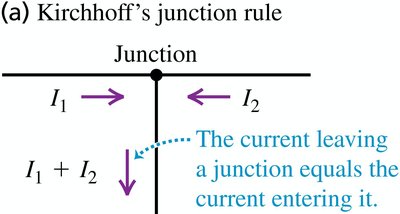
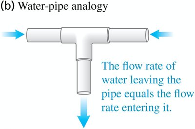
Junction Rule (Kirchhoff’s Current Law): The sum of currents entering a junction equals the sum of currents leaving the junction.
Loop Rule (Kirchhoff’s Voltage Law): The sum of the potential differences (voltage) around any closed loop is zero. This reflects the conservation of energy in the circuit.
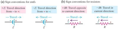
Sign Conventions: When applying the loop rule, assign positive or negative signs to emf and IR terms based on the direction of traversal relative to the current and emf polarity.
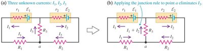
Reducing Unknowns: The junction rule can be used to reduce the number of unknown currents in a circuit.
Application of Kirchhoff’s Rules
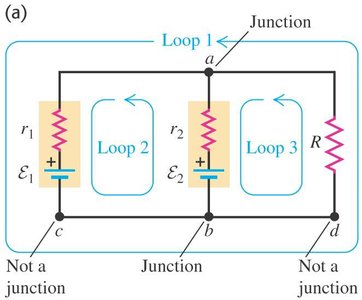
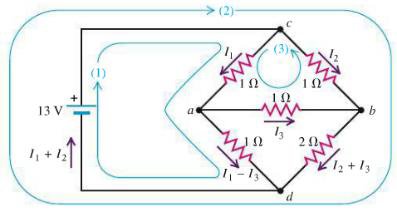
Kirchhoff’s rules are applied to analyze circuits with multiple batteries and resistors, such as series and parallel battery arrangements, and bridge circuits.
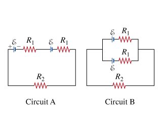
Series and Parallel Batteries: In series, the emf adds; in parallel, the current divides equally if resistances are equal.
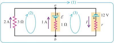
Multi-Loop Circuits: Apply the loop rule to each independent loop and the junction rule at each node to solve for unknown currents and voltages.
Bridge Circuits: These require simultaneous equations for current in each branch.
R-C Circuits: Charging and Discharging Capacitors
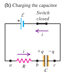
Charging a Capacitor
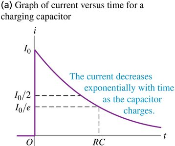
When a capacitor is connected in series with a resistor and a battery, the capacitor charges over time, and the current in the circuit decreases exponentially.
Initial Condition: At , the capacitor is uncharged and the current is maximum: .
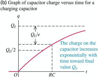
Charge on Capacitor: The charge increases exponentially toward its maximum value .
Current in Circuit: The current decreases exponentially as the capacitor charges.
Time Constant: is the time constant, representing the time for the charge (or current) to change significantly.

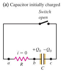
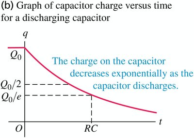
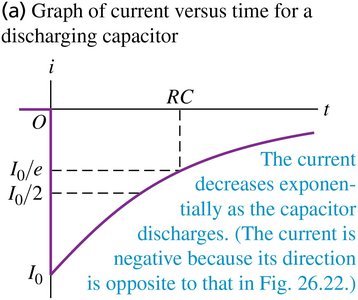
Discharging a Capacitor
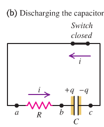
When a charged capacitor is connected across a resistor, it discharges, and both the charge and current decrease exponentially over time.
Initial Condition: At , the capacitor has charge and the current is maximum in the opposite direction.
Charge on Capacitor: The charge decreases exponentially toward zero.
Current in Circuit: The current also decreases exponentially, becoming zero as the capacitor fully discharges.
Time Constant: again determines the rate of discharge.
Summary Table: Key Equations for R-C Circuits
Process | Charge on Capacitor | Current in Circuit | Time Constant |
|---|---|---|---|
Charging | |||
Discharging |
Additional info: The exponential nature of charging and discharging processes is a hallmark of first-order differential equations in physics, and the time constant is a measure of how quickly the system responds to changes.
