 Back
BackDirect-Current Circuits: Series, Parallel, Kirchhoff’s Rules, and Applications
Study Guide - Smart Notes
 Tailored notes based on your materials, expanded with key definitions, examples, and context.
Direct-Current Circuits
Introduction to DC Circuits
Direct-current (DC) circuits are electrical circuits in which the current flows in a constant direction. These circuits are fundamental in electronics and physics, forming the basis for analyzing more complex electrical systems. DC circuits are commonly found in devices such as flashlights and automobile wiring systems, while household power typically uses alternating current (AC).
Resistors in Series and Parallel
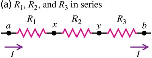
Resistors in Series
Resistors are said to be in series if they are connected end-to-end so that the same current flows through each resistor. The total or equivalent resistance of resistors in series is the sum of their individual resistances:
Current: The current is the same through all resistors in series.
Potential Difference: The total voltage across the series combination is the sum of the voltages across each resistor.
The equivalent resistance is given by:

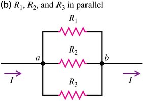
Resistors in Parallel
Resistors are in parallel if they are connected so that both ends of each resistor are directly connected to the same two points. In this configuration, the voltage across each resistor is the same, but the current can differ.
Current: The total current is the sum of the currents through each resistor.
Potential Difference: The voltage across each resistor is the same.
The equivalent resistance for parallel resistors is:
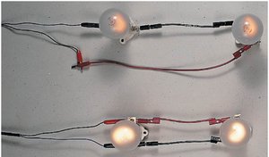
Series vs. Parallel: Applications
When connected to the same voltage source, resistors (or bulbs) in series draw less power and are dimmer than those in parallel, which draw more power and are brighter.
Combination Circuits
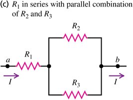
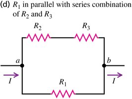
Many practical circuits involve combinations of series and parallel resistors. To analyze these, reduce the circuit stepwise to simpler series or parallel groups.
Example 1: Series with parallel combination.
Example 2: Parallel with series combination.
Kirchhoff’s Rules
Introduction to Kirchhoff’s Rules
For complex circuits that cannot be simplified into series or parallel combinations, Kirchhoff’s rules are used. These rules are based on the conservation of charge and energy.
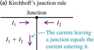
Kirchhoff’s Junction Rule
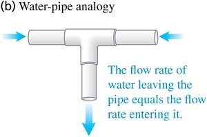
The junction rule states that the sum of currents entering a junction equals the sum of currents leaving the junction. This is a consequence of charge conservation.
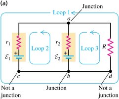

Kirchhoff’s Loop Rule
The loop rule states that the sum of the potential differences around any closed loop in a circuit is zero. This reflects the conservation of energy in electrical circuits.

Sign Conventions for the Loop Rule
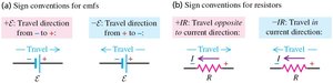
When applying the loop rule, use the following sign conventions:
For emf sources: Positive when moving from negative to positive terminal, negative otherwise.
For resistors: Positive when moving against the current, negative when moving with the current.

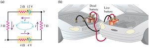
Single-Loop Circuits
Kirchhoff’s rules can be applied to single-loop circuits containing multiple batteries and resistors to determine current, voltage, and power.
Measuring Instruments in Circuits
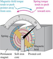
D’Arsonval Galvanometer
A galvanometer is an instrument for detecting and measuring small electric currents. It is the basis for ammeters and voltmeters.
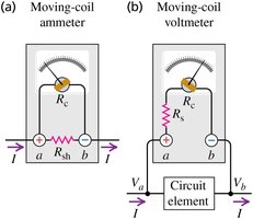
Ammeters and Voltmeters
An ammeter measures current and is connected in series with the circuit element. A voltmeter measures potential difference and is connected in parallel. Both use a galvanometer as their core component.
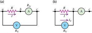
Using Ammeters and Voltmeters Together
Ammeters and voltmeters can be used together to measure resistance and power in a circuit. Corrections may be needed for accuracy, depending on the internal resistance of the meters.
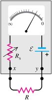
Ohmmeters
An ohmmeter measures resistance by passing a known current through the resistor and measuring the voltage drop. It typically consists of a meter, a variable resistor, and a battery.
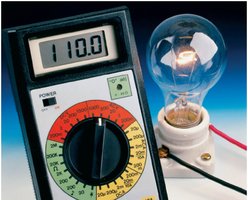
Digital Multimeters
Digital multimeters are versatile instruments that can measure voltage, current, and resistance over a wide range of values.
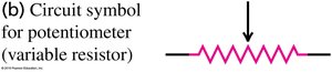
Potentiometers
A potentiometer is a variable resistor used to measure emf without drawing current from the source. It can also refer to any adjustable resistor in a circuit.
R-C Circuits (Resistor-Capacitor Circuits)
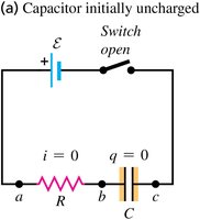
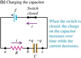
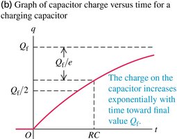
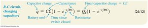
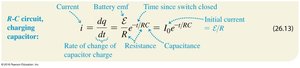
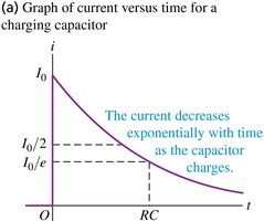
Charging a Capacitor
When a capacitor is charged through a resistor, the charge on the capacitor increases exponentially with time, while the current decreases exponentially. The time constant characterizes the rate of charging.
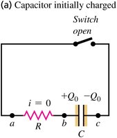
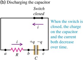
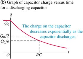
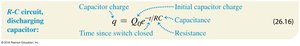
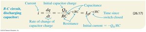
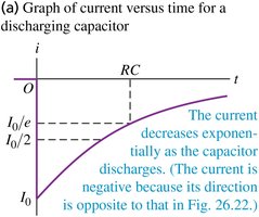
Discharging a Capacitor
When a charged capacitor is allowed to discharge through a resistor, both the charge and the current decrease exponentially with time, governed by the same time constant .
Power Distribution and Safety in Household Circuits
Power Distribution Systems
Household wiring distributes electrical power using a hot line (typically 120 V rms in the US) and a neutral line connected to ground. Fuses and circuit breakers protect against overloads.
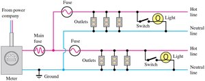
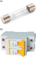
Circuit Overloads: Fuses and Circuit Breakers
Fuses and circuit breakers are safety devices that interrupt the circuit if the current exceeds a safe value. Fuses melt and must be replaced, while circuit breakers can be reset.
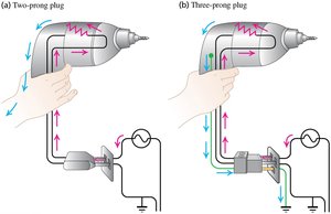
Three-Prong Plugs and Electrical Safety
Three-prong plugs provide an additional safety ground connection, reducing the risk of electric shock by directing stray currents safely to ground.
Configuration | Current | Voltage | Equivalent Resistance |
|---|---|---|---|
Series | Same through all resistors | Sum of individual voltages | |
Parallel | Sum of branch currents | Same across all resistors |
Additional info: The exponential behavior of charging and discharging capacitors is a key concept in electronics, with applications in timing circuits, filters, and signal processing. Kirchhoff’s rules are foundational for analyzing any electrical network, including those with multiple loops and branches.
