 Back
BackDirect-Current Circuits: Series, Parallel, Kirchhoff’s Rules, and RC Circuits
Study Guide - Smart Notes
 Tailored notes based on your materials, expanded with key definitions, examples, and context.
Direct-Current Circuits
Introduction
Direct-current (DC) circuits are fundamental in physics and engineering, involving the analysis of electric circuits powered by sources of constant electromotive force (emf). This chapter covers the behavior of resistors in series and parallel, the application of Kirchhoff’s rules, the use of electrical meters, and the analysis of circuits containing both resistors and capacitors (RC circuits).
Resistors in Series and Parallel
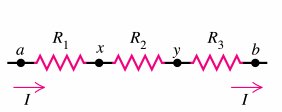
Resistors in Series
When resistors are connected end-to-end, they are said to be in series. The same current flows through each resistor, but the potential difference divides among them.
Current: Identical through all resistors:
Voltage: The total voltage is the sum of the voltages across each resistor:
Equivalent Resistance:
Property: The equivalent resistance is always greater than any individual resistance.
Application: If one device fails (open circuit), all devices in series become inoperative.
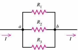
Resistors in Parallel
Resistors are in parallel if they are connected across the same two points. The voltage across each resistor is the same, but the current divides among the branches.
Voltage: Identical across all resistors:
Current: The total current is the sum of the branch currents:
Equivalent Resistance:
Property: The equivalent resistance is always less than the smallest individual resistance.
Application: Devices operate independently; if one is switched off, others remain on.
Comparison: Series vs. Parallel
Series: Current is the same; voltage divides; increases.
Parallel: Voltage is the same; current divides; decreases.
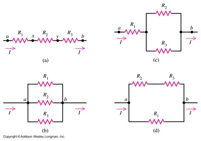
Examples of Series and Parallel Combinations
Series:
Parallel:
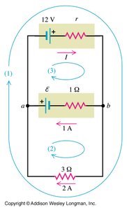
Kirchhoff’s Rules
Introduction to Kirchhoff’s Rules
For complex circuits that cannot be simplified using series and parallel combinations, Kirchhoff’s rules are used:
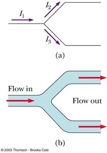
Junction Rule (Conservation of Charge): The sum of currents entering a junction equals the sum leaving it:
Loop Rule (Conservation of Energy): The sum of the potential differences around any closed loop is zero:
Applying Kirchhoff’s Rules
Assign current directions (arbitrary, but must be consistent).
Apply the junction rule at each node (except one, as the last is not independent).
Apply the loop rule for each independent loop.
Solve the resulting system of equations for unknown currents and voltages.
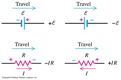
Sign Conventions for Loop Rule
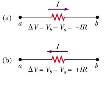
Traversing a resistor in the direction of current:
Traversing a resistor opposite to current:
Traversing an emf source from – to +:
Traversing an emf source from + to –:
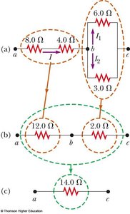
Example: Multi-Loop Circuit
Write one equation for each loop and one for each junction.
Solve for unknowns such as current through each resistor and emf values.
Electrical Measuring Instruments
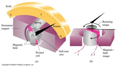
Galvanometer
A galvanometer is a sensitive instrument for detecting and measuring small electric currents. It consists of a coil in a magnetic field, which rotates in response to current, moving a pointer over a scale.
The deflection is proportional to the current.
Used as the basis for ammeters and voltmeters.
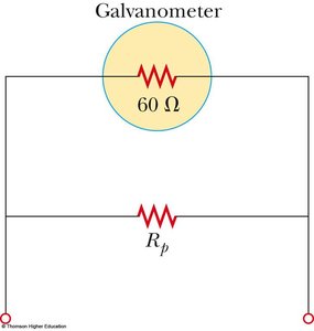
Ammeter
An ammeter measures current and must be connected in series with the circuit element. It is constructed by placing a low-resistance shunt in parallel with the galvanometer to allow most of the current to bypass the sensitive coil.
Ideal ammeter resistance: zero.
Shunt resistance is much less than the galvanometer resistance.
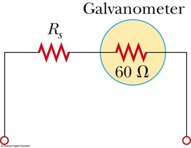
Voltmeter
A voltmeter measures potential difference and must be connected in parallel with the element. It is constructed by placing a large resistance in series with the galvanometer to minimize current draw.
Ideal voltmeter resistance: infinite.
Series resistance is much greater than the galvanometer resistance.
Household Wiring and Electrical Safety
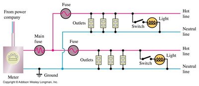
Household Wiring
Household circuits are wired in parallel so that each device operates independently. The system includes a live wire, a neutral wire (grounded), and often a ground wire for safety.
Potential difference between live and neutral: ~120 V (in the US).
Each circuit is protected by a circuit breaker or fuse.
Electrical Safety
Electric shock can cause burns or disrupt vital organ function.
Severity depends on current magnitude, duration, and path through the body.
Ground wires and ground-fault interrupters (GFI) are used for protection.
RC Circuits
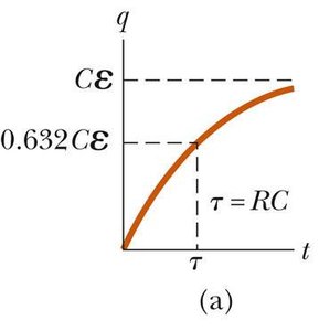
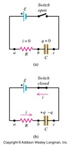
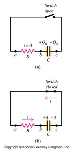
Charging a Capacitor in an RC Circuit
An RC circuit contains a resistor and a capacitor in series with a battery. When the circuit is closed, the capacitor charges over time, and the current decreases exponentially.
Charge on capacitor:
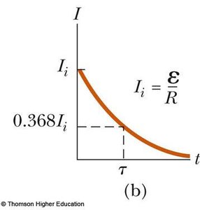
Current:
Time constant: (time to reach 63.2% of maximum charge)
Discharging a Capacitor in an RC Circuit
When a charged capacitor is allowed to discharge through a resistor, the charge and current decrease exponentially.
Charge:
Current:
After one time constant, charge drops to 36.8% of its initial value.
Summary Table: Series vs. Parallel Resistors
Property | Series | Parallel |
|---|---|---|
Current | Same through all | Divides among branches |
Voltage | Divides among resistors | Same across all |
Equivalent Resistance | ||
Effect of Open Circuit | All devices off | Others remain on |
Additional info: The notes above include expanded academic context, definitions, and examples to ensure completeness and clarity for exam preparation.
