 Back
BackElectric Charge, Electric Field, and Capacitance: Study Notes
Study Guide - Smart Notes
 Tailored notes based on your materials, expanded with key definitions, examples, and context.
Electric Charge and Methods of Charging
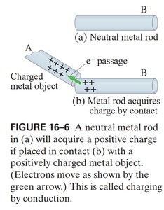
Charging by Conduction
Charging by conduction occurs when a charged object comes into contact with a neutral conductor, transferring charge directly. The neutral object acquires a charge of the same sign as the charged object.
Key Point 1: Electrons move from the neutral rod to the positively charged object, leaving the rod positively charged.
Key Point 2: The process is called charging by conduction.
Example: A neutral metal rod becomes positively charged when touched by a positively charged metal object.
Charging by Induction
Charging by induction involves bringing a charged object near a conductor, causing a separation of charges within the conductor without direct contact. If the conductor is then separated, each part retains a net charge.
Key Point 1: The conductor remains overall neutral, but charge separation occurs.
Key Point 2: Cutting the rod results in each part having a net charge.
Example: A metal rod is charged by induction and then split, resulting in two oppositely charged pieces.
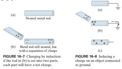
Inducing Charge with Grounding
When a conductor is connected to ground while a charged object is nearby, electrons can flow to or from the ground, leaving the conductor with a net charge after the ground connection is removed.
Key Point 1: Grounding allows charge transfer between the conductor and the earth.
Key Point 2: The conductor acquires a net charge after the ground is disconnected.
Example: Inducing a charge on a metal rod by grounding while a charged object is nearby.
Charge Separation in Nonconductors
When a charged object is brought near a nonconductor, it causes a redistribution of charges within the molecules of the nonconductor, resulting in polarization but not free movement of charge.
Key Point 1: Nonconductors experience charge separation at the molecular level.
Key Point 2: This process is called polarization.
Example: A charged rod induces polarization in a piece of plastic.
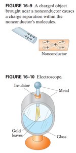
Electroscope and Detection of Charge
Electroscope Operation
An electroscope is a device used to detect the presence and sign of electric charge. It consists of metal leaves that diverge when charged.
Key Point 1: The leaves spread apart when the electroscope is charged.
Key Point 2: The device can be charged by conduction or induction.
Example: Charging an electroscope by touching it with a charged object.
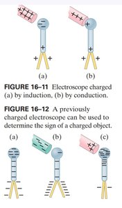
Charging Electroscope by Induction and Conduction
Electroscopes can be charged by induction (without contact) or conduction (with contact). The sign of the charge can be determined by observing the behavior of the leaves when a known charge is brought near.
Key Point 1: Induction causes charge separation; conduction transfers charge.
Key Point 2: The sign of the charge can be tested by bringing a charged object near a previously charged electroscope.
Example: Using an electroscope to determine if an object is positively or negatively charged.
Electric Force and Field
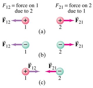
Coulomb's Law and Force Between Charges
The electric force between two point charges is described by Coulomb's Law. The force is attractive or repulsive depending on the signs of the charges.
Key Point 1: The force is given by , where is Coulomb's constant.
Key Point 2: Like charges repel; unlike charges attract.
Example: Calculating the force between a +1 µC and a -1 µC charge separated by 1 m.
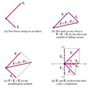
Vector Addition of Forces
When multiple forces act on a charge, their vector sum determines the net force. Vector addition can be performed using the tail-to-tip method or by resolving into components.
Key Point 1: Forces are vectors and must be added accordingly.
Key Point 2: The parallelogram method and component method are common techniques.
Example: Adding two perpendicular electric forces acting on a charge.
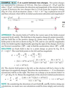
Electric Field Between Charges
The electric field at a point is the vector sum of the fields produced by all charges. The direction and magnitude depend on the positions and values of the charges.
Key Point 1: The electric field is given by , pointing away from positive and toward negative charges.
Key Point 2: The net field is the sum of individual fields.
Example: Calculating the electric field at a point between two charges.
Electric Field Lines and Equipotential Lines
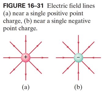
Electric Field Lines
Electric field lines visually represent the direction and strength of the electric field. Lines start on positive charges and end on negative charges; their density indicates field strength.
Key Point 1: Field lines are tangent to the field direction at every point.
Key Point 2: The number of lines is proportional to the magnitude of the charge.
Example: Field lines around a single positive or negative charge.
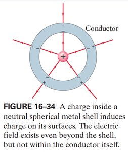
Field Lines in Conductors and Spherical Shells
When a charge is placed inside a conductor or a spherical shell, the field lines are altered. The field exists outside the shell but not within the conductor itself.
Key Point 1: Charges induce surface charge distributions in conductors.
Key Point 2: The electric field inside a conductor is zero.
Example: A charge inside a neutral spherical metal shell.
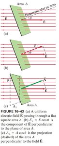
Electric Flux and Area Orientation
Electric flux is the product of the electric field and the area perpendicular to the field. The orientation of the area relative to the field affects the flux calculation.
Key Point 1: Flux is maximum when the area is perpendicular to the field.
Key Point 2: The component of the field perpendicular to the area is .
Example: Calculating flux through a tilted surface.
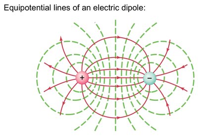
Equipotential Lines of an Electric Dipole
Equipotential lines are lines where the electric potential is constant. For a dipole, these lines form closed loops around the charges, perpendicular to the field lines.
Key Point 1: Equipotential lines never cross electric field lines.
Key Point 2: The potential is constant along each equipotential line.
Example: Equipotential lines around a dipole.
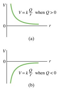
Electric Potential vs. Distance
The electric potential due to a point charge varies inversely with distance. The sign of the charge determines whether the potential increases or decreases with distance.
Key Point 1: for a point charge.
Key Point 2: Positive charges produce decreasing potential with distance; negative charges produce increasing potential.
Example: Graphs of potential vs. distance for positive and negative charges.
Capacitance and Capacitor Networks
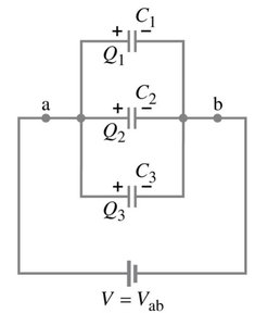
Capacitors in Parallel
When capacitors are connected in parallel, their equivalent capacitance is the sum of their individual capacitances. The voltage across each capacitor is the same.
Key Point 1:
Key Point 2: Each capacitor stores charge proportional to its capacitance.
Example: Three capacitors in parallel across a battery.
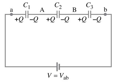
Capacitors in Series
For capacitors in series, the reciprocal of the equivalent capacitance is the sum of the reciprocals of the individual capacitances. The charge on each capacitor is the same.
Key Point 1:
Key Point 2: The voltage divides among the capacitors.
Example: Three capacitors in series across a battery.
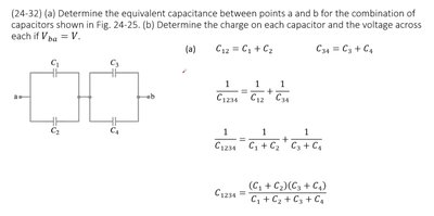
Mixed Capacitor Networks
Capacitor networks can involve both series and parallel combinations. The equivalent capacitance is found by reducing the network step by step.
Key Point 1: Combine parallel and series sections separately.
Key Point 2: Use the formulas for series and parallel as appropriate.
Example: A network with two capacitors in series, combined in parallel with a third capacitor.
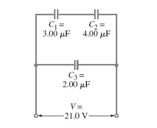
Complex Capacitance Calculation
For more complex networks, equivalent capacitance can be calculated using stepwise reduction and appropriate formulas.
Key Point 1: Combine capacitors in parallel and series stepwise.
Key Point 2: For four capacitors, use .
Example: Calculating equivalent capacitance for a network with four capacitors.
 *Additional info: The notes expand on brief points and include academic context for clarity and completeness. All images included are directly relevant to the adjacent explanations, reinforcing key concepts in electric charge, field, and capacitance.*
