 Back
BackElectric Circuits, Capacitance, and Electromagnetic Induction: Key Concepts and Problem-Solving Strategies
Study Guide - Smart Notes
 Tailored notes based on your materials, expanded with key definitions, examples, and context.
Electric Circuits: Series and Parallel Connections
Understanding Series and Parallel Circuits
Electric circuits can be constructed by connecting components such as resistors or capacitors in series or in parallel. The configuration affects the total (equivalent) resistance or capacitance, as well as how current and voltage are distributed in the circuit.
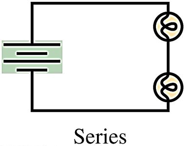
Series Connection: Components are connected end-to-end so that the same current flows through each component.
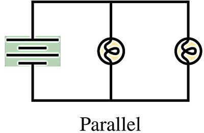
Parallel Connection: Components are connected across the same two points, so each component has the same voltage across it.
Equivalent Resistance in Series and Parallel
The equivalent resistance of a group of resistors depends on whether they are connected in series or parallel:
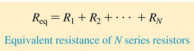
Series: The total resistance is the sum of the individual resistances.
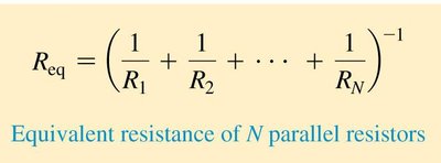
Parallel: The reciprocal of the total resistance is the sum of the reciprocals of the individual resistances.
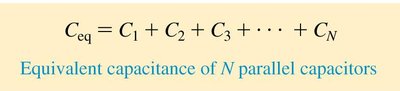
Equivalent Capacitance in Series and Parallel
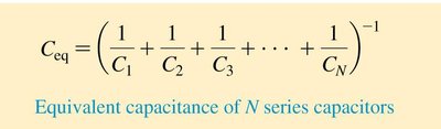
Capacitors also combine differently depending on their configuration:
Parallel: The total capacitance is the sum of the individual capacitances.
Series: The reciprocal of the total capacitance is the sum of the reciprocals of the individual capacitances.
Electromagnetic Induction: Lenz's Law
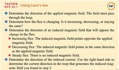
Applying Lenz's Law
Lenz's law is a fundamental principle for determining the direction of induced currents in a loop when the magnetic flux through the loop changes. It ensures that the induced current always opposes the change in magnetic flux.
Determine the direction of the applied magnetic field. The field must pass through the loop.
Determine how the flux is changing. Is it increasing, decreasing, or staying the same?
Determine the direction of the induced magnetic field that will oppose the change in the flux:
Increasing flux: The induced magnetic field points opposite the applied magnetic field.
Decreasing flux: The induced magnetic field points in the same direction as the applied magnetic field.
Steady flux: There is no induced magnetic field.
Determine the direction of the induced current. Use the right-hand rule to determine the current direction in the loop that generates the induced magnetic field found in step 3.
Example: Induced Current in a Loop
If the magnetic field through a loop is increasing into the page, the induced current will flow in a direction that creates a magnetic field out of the page (opposing the increase).
If the magnetic field is decreasing, the induced current will flow to reinforce the field (in the same direction as the original field).
Additional info: These principles are essential for analyzing and solving problems involving electric circuits and electromagnetic induction, as covered in introductory college physics courses.
