Back
BackLec 9
Study Guide - Smart Notes
 Tailored notes based on your materials, expanded with key definitions, examples, and context.
Capacitors in Series and Parallel
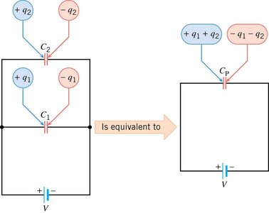
Capacitors in Parallel
When capacitors are connected in parallel, the total (equivalent) capacitance is the sum of the individual capacitances. Each capacitor experiences the same voltage, and the total charge stored is the sum of the charges on each capacitor.
Formula:
Voltage:
Charge:
Application: Used when increased capacitance is needed without increasing voltage rating.
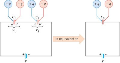
Capacitors in Series
For capacitors in series, the reciprocal of the total capacitance is the sum of the reciprocals of the individual capacitances. The same charge passes through each capacitor, but the voltage divides among them.
Formula:
Charge:
Voltage:
Application: Used to increase voltage rating without increasing capacitance.
Example Calculation: Equivalent Capacitance and Energy Storage
Given two capacitors, and :
Series:
Parallel:
Energy Stored:
Example: For , ,
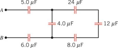
Complex Capacitor Networks
Capacitor networks may involve combinations of series and parallel arrangements. To find the equivalent capacitance, reduce the network stepwise using the rules above.
Step 1: Identify series and parallel groups.
Step 2: Calculate equivalent capacitance for each group.
Step 3: Combine results to find total capacitance between points.

Measurement of Current and Voltage in DC Circuits
Devices Used for Measurement
Current and voltage in DC circuits are measured using ammeters and voltmeters. These devices can be analog or digital, but analog devices are often easier to understand from basic principles.
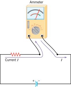
Ammeter: Measures current flowing through a circuit.
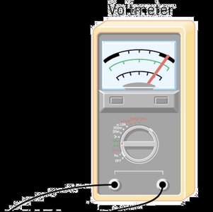
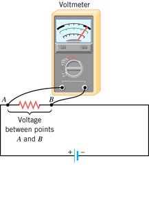
Voltmeter: Measures voltage across a device or circuit segment.
Galvanometer: An analog device that detects current by needle deflection; forms the basis for both ammeters and voltmeters.
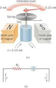
Using a Galvanometer as an Ammeter
To measure large currents, a galvanometer is modified by adding a parallel shunt resistor. Most of the current bypasses the galvanometer, protecting it from overload.
Shunt Resistance Formula:
Equivalent Resistance:
Placement: Ammeter is inserted in series with the circuit.
Requirement: Ammeter must have low resistance to minimize circuit disturbance.
Using a Galvanometer as a Voltmeter
To measure voltage, a galvanometer is modified by adding a series resistor. This limits the current through the galvanometer, allowing it to measure higher voltages safely.
Series Resistance Formula:
Equivalent Resistance:
Placement: Voltmeter is connected in parallel across the points of interest.
Requirement: Voltmeter must have high resistance to minimize circuit disturbance.
Extension Cord Hazards and Circuit Safety
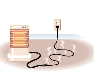
Extension Cord Hazards
Using extension cords with electric heaters can be hazardous if the wire gauge is too large (thin wire). Thicker wires (smaller gauge number) are safer because they can carry higher currents without overheating.
Wire Gauge: Lower gauge number means thicker wire and higher current rating.
Example: To power a 1800 W heater at 120 V, a current of 15 A is required. Use a 14-gauge wire for safety.
Formula:

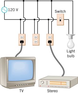
Protecting Circuits with Fuses
Fuses protect circuits by breaking the connection if the current exceeds a safe value. Appliances connected in parallel share the total current, which must not exceed the fuse rating.
Fuse: Thin wire that melts when current is too high, opening the circuit.
Parallel Appliances: Total current is the sum of individual appliance currents.
Formula:
Example: Appliances drawing 6.7 A total on a 10 A fuse: safe operation.
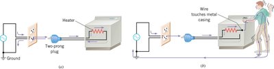
Safety in Grounding Electrical Devices
Proper grounding reduces the risk of electric shock by providing a safe path for current in case of a fault. Three-prong plugs and grounded outlets are standard safety features.
Grounding: Connects device casing to earth ground, preventing dangerous voltages.
Three-Prong Plug: Includes a ground connection for safety.
Application: Essential for appliances with metal casings or high power.