 Back
BackElectric Circuits: Current, Resistance, and Circuit Analysis Ch 28
Study Guide - Smart Notes
 Tailored notes based on your materials, expanded with key definitions, examples, and context.
Electric Current and Conductivity
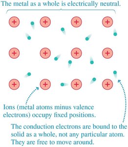
Conduction Electrons in Metals
In metallic solids, the outer-shell electrons are not bound to individual atoms but are free to move throughout the material. This forms an 'electron gas' responsible for electrical conductivity.
Ions (metal atoms minus valence electrons) occupy fixed positions in the lattice.
Conduction electrons are bound to the solid as a whole, not to any particular atom, and are free to move around.
The metal as a whole remains electrically neutral.
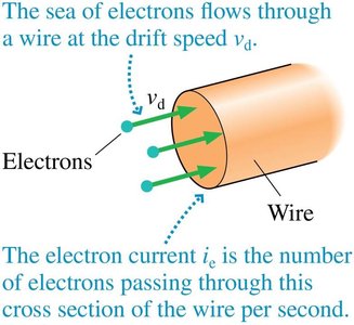
Drift Velocity and Current
When an electric field is applied, conduction electrons drift slowly opposite to the field direction, creating an electric current.
Drift velocity () is the average velocity of electrons due to the electric field, typically much slower than their random thermal motion.
Current () is defined as the amount of charge passing through a cross-section of the wire per second.
Formula: where is the electron charge, is the number density of electrons, is drift velocity, and is cross-sectional area.
Because electrons are negatively charged, conventional current direction is opposite to electron flow.
Unit: 1 ampere (A) = 1 coulomb/second (C/s).
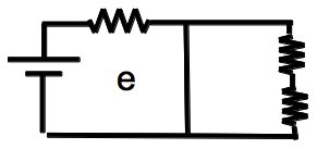
Basic Circuit Elements and Diagrams
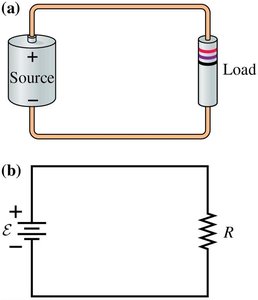
Simple Circuit Representation
Electric circuits are composed of sources (batteries), loads (resistors, bulbs), and connecting wires. Circuit diagrams use standardized symbols to represent these elements.
Source: Provides a fixed potential difference (voltage).
Load: Consumes electrical energy (e.g., resistor, bulb).
Wire: Conducts current between elements.
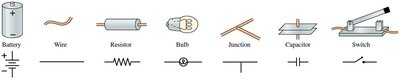
Circuit Symbols
Standardized symbols are used in circuit diagrams to simplify analysis and communication.
Battery: Source of EMF
Wire: Conductive path
Resistor: Limits current
Bulb: Converts electrical energy to light
Junction: Point where wires meet
Capacitor: Stores charge
Switch: Opens/closes circuit
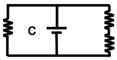
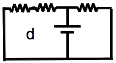
Series and Parallel Circuits
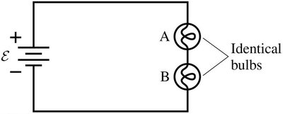
Series Circuits
In a series circuit, all elements are connected end-to-end, so the same current flows through each element.
Current is the same through all components.
Voltage divides among the elements according to their resistance.
Example: Two identical bulbs in series will have equal brightness.
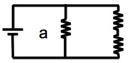
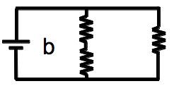
Parallel Circuits
In a parallel circuit, elements are connected across the same two points, so each receives the same voltage.
Voltage is the same across all parallel branches.
Current divides among the branches according to their resistance.
Example: Bulbs in parallel are brighter than in series because each receives full battery voltage.
Analyzing Circuit Diagrams
Identifying Circuit Connections
Circuit diagrams may look different but represent the same electrical connections. The key is to identify which elements are in series or parallel.
Series: Current must pass through each element sequentially.
Parallel: Elements are connected across the same two points.
Kirchhoff's Laws
Kirchhoff's Junction Law
The sum of currents entering a junction equals the sum of currents leaving the junction, reflecting conservation of charge.
Mathematically:
Kirchhoff's Loop Law
The sum of potential differences (voltage) around any closed loop in a circuit is zero.
Mathematically:
Used to analyze complex circuits with multiple loops and branches.
Ohm's Law and Resistance
Ohm's Law
Ohm's law relates the current through a conductor to the voltage across it and its resistance.
Formula:
Resistance () is measured in ohms ().
Equivalent Resistance
To simplify circuit analysis, resistors in series and parallel can be replaced by a single equivalent resistor.
Series:
Parallel:
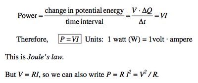
Power in Electric Circuits
Power Dissipation
Power in a circuit element is the rate at which electrical energy is converted to other forms (e.g., heat, light).
Formula:
Alternative forms:
Unit: watt (W)
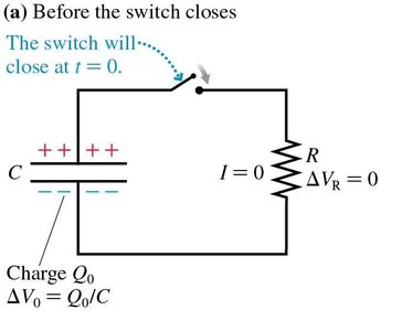
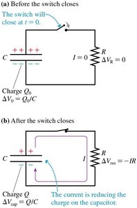
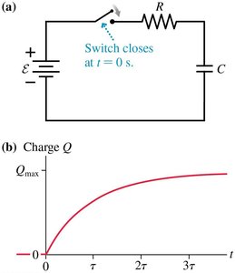
RC Circuits
Charging and Discharging a Capacitor
RC circuits consist of a resistor and capacitor in series or parallel. The charging and discharging of the capacitor follow exponential laws.
Charge on capacitor: (discharging), (charging)
Current:
Time constant:
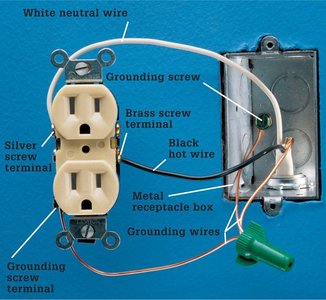
Grounding in Circuits
Purpose of Grounding
Grounding provides a reference point for circuit potential and enhances safety by preventing unwanted voltage differences between the circuit and the earth.
Protects users and equipment from electrical faults.
Ensures stable operation of electrical systems.
Summary Table: Circuit Elements and Their Functions
Element | Symbol | Function |
|---|---|---|
Battery | — | Provides EMF (voltage) |
Wire | — | Conducts current |
Resistor | — | Limits current, dissipates energy |
Bulb | — | Converts electrical energy to light |
Junction | — | Connects multiple wires |
Capacitor | — | Stores electrical energy |
Switch | — | Opens/closes circuit |
