 Back
BackElectric Circuits: Power, Series and Parallel Circuits, Kirchhoff’s Rules, and RC Circuits
Study Guide - Smart Notes
 Tailored notes based on your materials, expanded with key definitions, examples, and context.
Electric Circuits: Power, Series and Parallel Circuits, Kirchhoff’s Rules, and RC Circuits
Power in Electric Circuits
Power in an electric circuit is the rate at which energy is transferred or converted. It is a fundamental concept for understanding how electrical devices consume energy and how circuits are designed for safety and efficiency.
Definition: Power (P) is the rate of energy transfer, mathematically given by , where is the change in energy and is the time interval.
Unit: The SI unit of power is the watt (W), where .
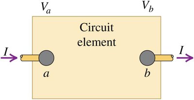
In Circuits: For a circuit element with voltage across it and current through it, .
Alternative Forms: Using Ohm’s law (), power can also be written as or .
Example: For a wire with and , .


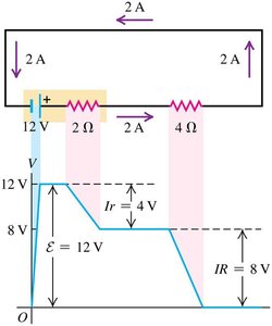
Potential Changes in Circuits
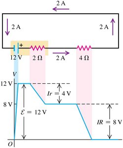
As current flows through a circuit, the electric potential changes depending on the elements encountered. Batteries increase potential, while resistors decrease it.
Potential Rise: Occurs when current passes through a battery from the negative to the positive terminal.
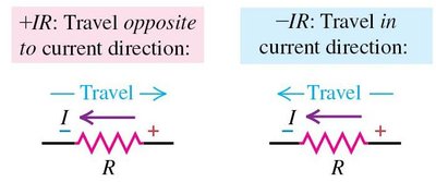
Potential Drop: Occurs when current passes through a resistor.
Conservation: The total potential change around a closed loop is zero.
Series and Parallel Circuits
Series Circuits
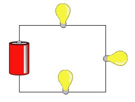
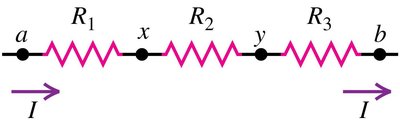
In a series circuit, all components are connected end-to-end, forming a single path for current flow.
Current: The same through all components: .
Voltage: The total voltage is the sum of the voltage drops: .
Resistance: The equivalent resistance is the sum of individual resistances: .
Example: For resistors of , , and in series with a battery, , , and voltage drops are , , and respectively.

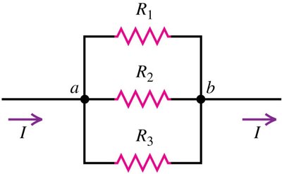
Parallel Circuits
In a parallel circuit, components are connected across the same two points, creating multiple paths for current.
Voltage: The same across all branches: .
Current: The total current is the sum of the branch currents: .
Resistance: The reciprocal of the equivalent resistance is the sum of the reciprocals of individual resistances: .
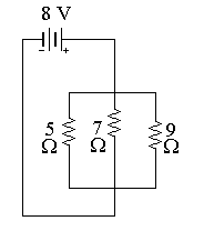
Example: For resistors of , , and in parallel with an battery, , and the total current is .

Series-Parallel Combinations
Complex circuits often contain both series and parallel components. These can be simplified stepwise by reducing series and parallel groups to their equivalent resistances.
Strategy: Reduce the circuit from the inside out, combining series and parallel resistors step by step.
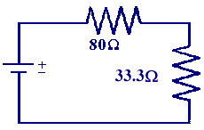
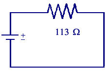
Example: An resistor in series with the parallel combination of and resistors has .
Kirchhoff’s Rules
Kirchhoff’s Junction Rule
The junction rule is based on the conservation of electric charge. It states that the sum of currents entering a junction equals the sum of currents leaving the junction.
Mathematical Form: at any junction.
Application: Used to analyze complex circuits with multiple branches.
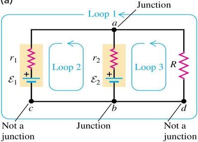

Kirchhoff’s Loop Rule
The loop rule is based on the conservation of energy. It states that the sum of the potential differences around any closed loop in a circuit is zero.
Mathematical Form: for any closed loop.
Sign Conventions: When traversing a loop, potential increases across batteries (from - to +) and decreases across resistors (in the direction of current).

Solving Complex Circuits
For circuits that cannot be simplified to series or parallel combinations, Kirchhoff’s rules are used to set up systems of equations for the unknown currents.
Steps:
Assign current directions (arbitrary; negative result means opposite direction).
Apply the junction rule at each junction.
Apply the loop rule for each independent loop.
Solve the resulting system of equations.
Real Batteries and Internal Resistance
Real batteries are not ideal and possess internal resistance, which affects the terminal voltage when a current is drawn.
Equation: where is the emf, is the current, and is the internal resistance.
Implication: The terminal voltage drops as the current increases due to internal resistance.
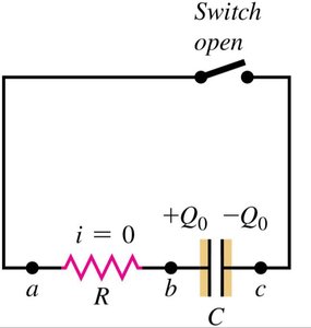
RC Circuits: Charging and Discharging Capacitors
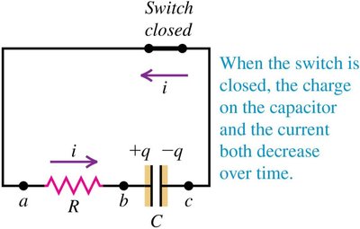
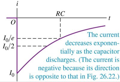
Discharging a Capacitor
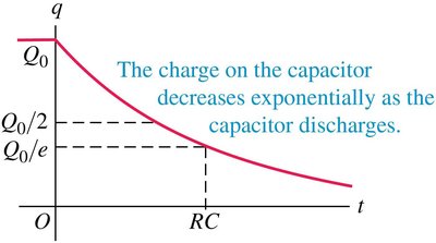
When a charged capacitor is connected across a resistor, it discharges over time, and both the charge and current decrease exponentially.
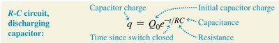
Charge: , where is the initial charge, is resistance, is capacitance, and is time.
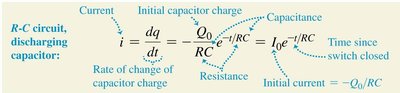
Current: (negative sign indicates direction).
Time Constant: determines the rate of decay.
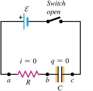
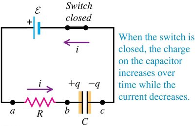
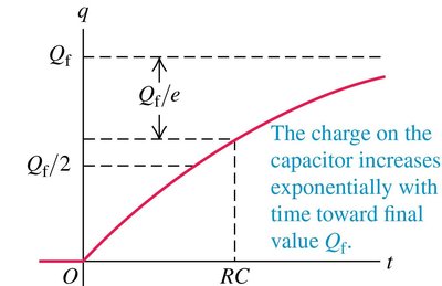
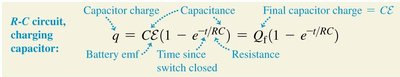
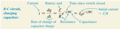
Charging a Capacitor
When a capacitor is connected to a battery through a resistor, it charges up over time, with the charge increasing and the current decreasing exponentially.
Charge: , where is the final charge.
Current: , where is the emf of the battery.
Time Constant: determines the rate of charging.
Household Circuits and Safety
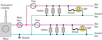
Power Distribution Systems
Household wiring distributes electric power from the main supply to various outlets and appliances. Safety devices such as fuses and circuit breakers protect against overloads.
Hot and Neutral Lines: The hot line carries the alternating voltage, while the neutral line is grounded.
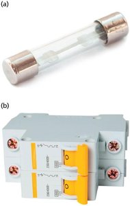
Fuses: Melt and break the circuit if current exceeds a safe value.
Circuit Breakers: Electromechanical devices that interrupt the circuit when overloaded and can be reset.
Measuring Instruments
Digital multimeters are versatile instruments used to measure voltage, current, and resistance in circuits, essential for diagnostics and troubleshooting.
Additional info: The notes above cover the main concepts from the provided materials, including power in circuits, series and parallel resistor combinations, Kirchhoff’s rules, RC circuits, and household wiring safety. All equations are provided in LaTeX format, and only directly relevant images are included to reinforce the explanations.
