 Back
BackLec 7
Study Guide - Smart Notes
 Tailored notes based on your materials, expanded with key definitions, examples, and context.
Electric Power in Circuits
Definition and Calculation of Electric Power
Electric power is the rate at which electrical energy is transferred by an electric circuit. It is a fundamental concept in understanding how electrical devices operate and consume energy.
Electric Power (P): The power delivered to a circuit is given by the product of the current (I) and the voltage (V) across the circuit.
SI Unit: The watt (W), where 1 W = 1 J/s.
For resistive devices, power can also be expressed using Ohm's Law:
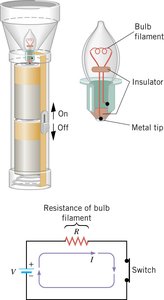
Example: A flashlight with a current of 0.40 A and a voltage of 3.0 V has a power output of W. The energy dissipated in 5.5 minutes (330 s) is J.
Series Wiring in Electric Circuits
Characteristics of Series Circuits
In a series circuit, electrical devices are connected so that the same current flows through each device. The total resistance is the sum of the individual resistances.
Current: The same through all components.
Total Resistance:
Voltage Division: The total voltage is divided among the resistors.
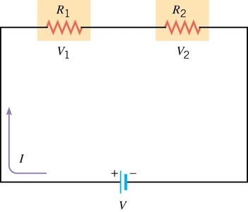
Example: Two resistors, 6.00 Ω and 3.00 Ω, in series with a 12.0 V battery:
Total resistance: Ω
Current: A
Voltage across 6.00 Ω: V
Voltage across 3.00 Ω: V
Parallel Wiring in Electric Circuits
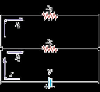
Characteristics of Parallel Circuits
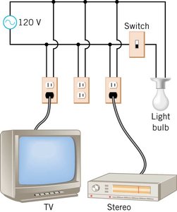
In parallel wiring, devices are connected so that the same voltage is applied across each device. The total current is the sum of the currents through each branch, and the equivalent resistance is always less than the smallest individual resistance.
Voltage: The same across all branches.
Total Current:
Equivalent Resistance:

Example: Household outlets are wired in parallel so each appliance receives the same voltage, and a failure in one does not affect the others.
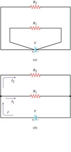
Example: Main and remote stereo speakers (4.00 Ω and 8.00 Ω) connected in parallel to a 6.00 V source:
Equivalent resistance: Ω
Total current: A
Series-Parallel Circuits
Combining Series and Parallel Elements
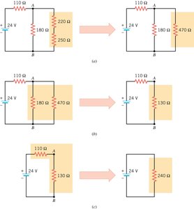
Many practical circuits contain both series and parallel components. To analyze these, reduce the circuit stepwise by replacing series and parallel groups with their equivalents.
Series:
Parallel:
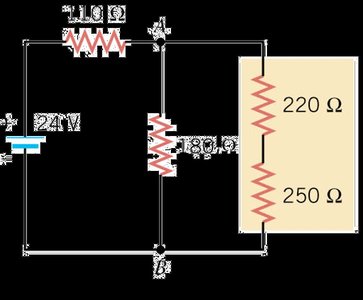
Example: A circuit with 110 Ω, 180 Ω, 220 Ω, and 250 Ω resistors and a 24 V battery:
Stepwise reduction yields an equivalent resistance of 240 Ω and a total current of 0.10 A.
Internal Resistance and Terminal Voltage
Understanding Internal Resistance
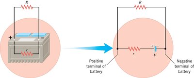
All real batteries and generators have some internal resistance, which reduces the voltage available to the external circuit. The actual voltage across the battery terminals is called the terminal voltage.
emf (Electromotive Force): The ideal voltage of the battery.
Terminal Voltage: , where is the internal resistance and is the current.
Example: A 12.0 V car battery with 0.010 Ω internal resistance:
At 10.0 A: V
At 100.0 A: V
High current draw (e.g., starting a car) causes the terminal voltage to drop, dimming headlights.
Summary Table: Series vs. Parallel Circuits
Property | Series Circuit | Parallel Circuit |
|---|---|---|
Current | Same through all components | Divided among branches |
Voltage | Divided among components | Same across all branches |
Resistance | Adds: | Reciprocal sum: |
Failure Effect | Break disables entire circuit | Other branches remain active |
