 Back
BackWeek 5 Lec. 1
Study Guide - Smart Notes
 Tailored notes based on your materials, expanded with key definitions, examples, and context.
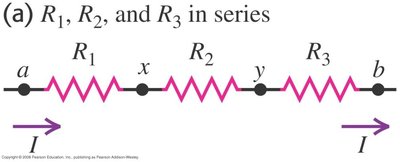
Resistors in Series
Series Connection of Resistors
When resistors are connected in series, the same current flows through each resistor, but the voltage across each resistor may differ depending on its resistance. The total resistance is the sum of individual resistances.
Current: (same through all resistors)
Voltage: (sum of voltages across each resistor equals total voltage)
Equivalent Resistance:
Formula for resistors of different lengths:
Example: If , , and V, then , A, V, V.
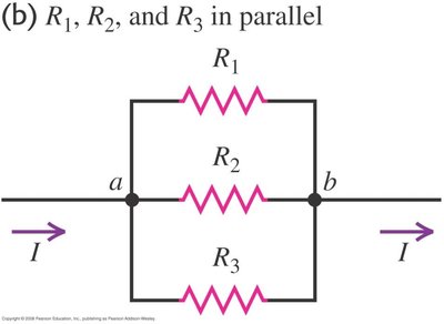
Resistors in Parallel
Parallel Connection of Resistors
In a parallel arrangement, the voltage across each resistor is the same, but the current divides among the resistors according to their resistance values. The equivalent resistance is always less than the smallest individual resistance.
Voltage: (same across all resistors)
Current: (sum of currents through each branch)
Equivalent Resistance:
Example: For , , V, , A.
Series vs. Parallel Arrangements
Comparison of Equivalent Resistance
Parallel arrangements always have a smaller equivalent resistance than series arrangements for the same resistors. This is because parallel paths provide more ways for current to flow.
Series:
Parallel:
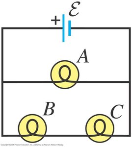
Brightness in Parallel Circuits
Light Bulb Example
When identical bulbs are connected in parallel, the bulbs in parallel branches (B and C) are brighter than the bulb in the series branch (A), because they receive the full voltage and more current flows through them.
Current in Parallel Circuits
Effect of Adding More Resistors
As more resistors are added in parallel, the total resistance decreases, allowing more current to flow through the circuit.
Key Point: Adding parallel resistors decreases the equivalent resistance.
Circuit Elements
Branches, Junctions, and Loops
Understanding the structure of circuits is essential for analysis. A branch is a single circuit element, a junction is where branches meet, and a loop is any closed path in the circuit.
Branch: A single element with two ends (e.g., resistor, capacitor)
Junction (Node): Point where three or more branches meet
Loop: Any closed path in the circuit
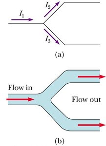
Kirchhoff’s Laws
Kirchhoff’s Junction Rule
The sum of currents entering a junction equals the sum of currents leaving the junction. This is a statement of conservation of charge.
Mathematical Form:
Physical Meaning: Charge cannot accumulate at a node.
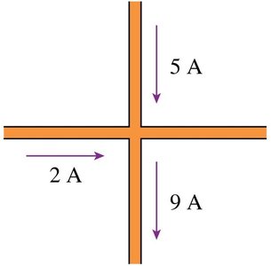
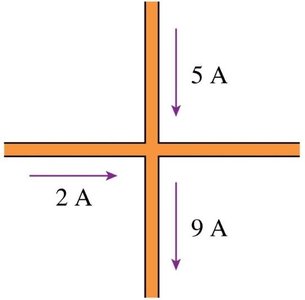
Kirchhoff’s Junction Rule Example
Given currents of 5 A and 9 A entering a junction and 2 A leaving, the current in the fourth wire must be 12 A leaving to satisfy the junction rule.
Kirchhoff’s Loop Rule
The algebraic sum of the changes in potential around any closed loop is zero. This is a statement of conservation of energy in electrical circuits.
Mathematical Form: around a closed loop
Application: Used to analyze circuits with multiple loops and voltage sources
Example: Moving clockwise around a loop with two batteries and two resistors:
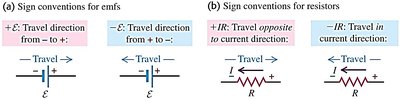
Sign Conventions in Loop Rule
When traversing a circuit:
Voltage gains (battery from - to +): positive sign
Voltage drops (battery from + to - or across resistors in current direction): negative sign
Direction of current is arbitrary; negative result means actual current flows opposite to chosen direction
Kirchhoff Circuit Analysis Tips
Steps for Solving Circuits
Sketch the circuit diagram
Simplify using equivalent resistors
Label currents with assumed directions
Apply Junction Rule to label currents
Choose independent loops
Apply Loop Rule to each loop
Solve the resulting simultaneous linear equations
Additional info: These concepts are foundational for analyzing direct-current circuits, as covered in Chapter 26 of college physics.
