 Back
BackLec 8
Study Guide - Smart Notes
 Tailored notes based on your materials, expanded with key definitions, examples, and context.
Electric Circuits
Series and Parallel Circuits
Electric circuits can be constructed by connecting resistors in series, parallel, or a combination of both. Understanding how to calculate the equivalent resistance in these configurations is essential for analyzing circuit behavior.
Series Connection: Resistors are connected end-to-end, so the same current flows through each resistor. The total (equivalent) resistance is the sum of individual resistances:
Parallel Connection: Resistors are connected across the same two points, so the voltage across each resistor is the same. The reciprocal of the total resistance is the sum of the reciprocals of the individual resistances:
Combination Circuits: Many practical circuits involve both series and parallel elements. To analyze these, reduce the circuit stepwise by replacing series and parallel groups with their equivalent resistances.
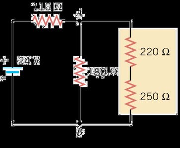
Example: For a circuit with a 24 V battery and resistors of 110 Ω, 180 Ω, 220 Ω, and 250 Ω, the equivalent resistance is found by reducing parallel and series combinations stepwise. The total current supplied by the battery is then .
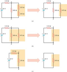
Calculation Example:
Combine 220 Ω and 250 Ω in series:
Combine with 180 Ω in parallel:
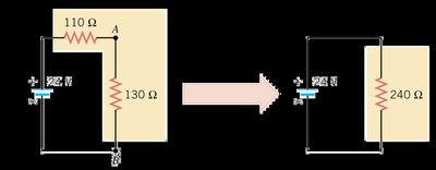
Add 110 Ω in series:
Total current:
Voltage between points A and B (across 130 Ω):
Internal Resistance and Terminal Voltage
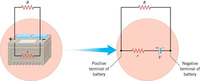
Real batteries and generators have internal resistance, which affects the voltage available to the external circuit. The terminal voltage is the actual voltage measured across the battery's terminals when a current is drawn.
emf (Electromotive Force): The ideal voltage provided by a battery when no current flows.
Internal Resistance (r): The resistance inside the battery, causing a voltage drop as current flows.
Terminal Voltage (V): Given by where is the current.
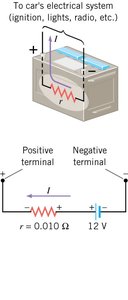
Example: A car battery with emf 12.0 V and internal resistance 0.010 Ω:
For A: V
For A: V
Application: When starting a car, the large current drawn by the starter reduces the terminal voltage, causing headlights to dim.
Kirchhoff’s Rules
For complex circuits that cannot be simplified by series and parallel reductions alone, Kirchhoff’s Rules are used to analyze the currents and voltages.
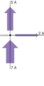
Junction Rule (Conservation of Charge): The sum of currents entering a junction equals the sum of currents leaving the junction.
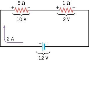
Loop Rule (Conservation of Energy): The sum of the potential differences (voltage rises and drops) around any closed loop is zero.
Reasoning Strategy:
Assign current directions in each branch (arbitrary; negative result means opposite direction).
Mark polarities across resistors and batteries consistent with current direction and emf.
Apply the junction and loop rules to write equations for the unknowns.
Solve the simultaneous equations for the unknown currents and voltages.
Example: Applying Kirchhoff’s Rules
Consider a circuit with two batteries and two resistors. By applying the loop rule, you can set up an equation for the current:
Solve for to find the current in the circuit.

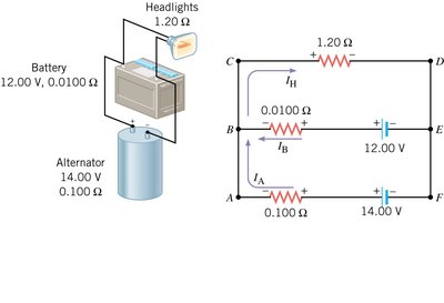
Multi-Loop Circuits: Car Electrical System Example
In automotive electrical systems, multiple sources (battery and alternator) and loads (headlights) are present. Kirchhoff’s rules allow calculation of the current through each component.
Apply the junction rule at a node to relate the currents.
Apply the loop rule to different loops to set up equations for the unknown currents.
Solve the system of equations to find the current through the battery, alternator, and headlights.
Rule | Statement | Equation |
|---|---|---|
Junction Rule | Sum of currents into a junction equals sum out | |
Loop Rule | Sum of potential changes around a closed loop is zero |
Additional info: In real-world applications, such as automotive circuits, the analysis of multi-loop circuits using Kirchhoff’s rules is essential for understanding how different components interact and how voltage drops affect device performance.
