 Back
BackElectric Current and DC Circuits: Comprehensive Study Notes
Study Guide - Smart Notes
 Tailored notes based on your materials, expanded with key definitions, examples, and context.
Electric Current and DC Circuits
Introduction to Electric Current
Electric current is a fundamental concept in physics, describing the flow of electric charge through a conductor. It is essential for understanding how electrical circuits operate and is measured in amperes (A).
Definition: Electric current (I) is the rate at which charge (ΔQ) flows through a point in a conductor per unit time (Δt).
Formula:
Unit: 1 ampere (A) = 1 coulomb/second (C/s)
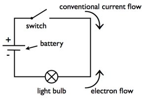
Conventional Current: Defined as the flow of positive charge, even though electrons (negative charges) are the actual charge carriers in metals. The direction of conventional current is opposite to electron flow.
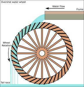
Analogy: Water flowing through a pipe is analogous to electric current flowing through a wire. The water pressure is similar to electric potential (voltage).
Electric Circuits
An electric circuit provides a closed path for current to flow between two terminals of a voltage source, such as a battery.
Complete Path: For current to flow, the circuit must be closed (no gaps).
Conductors: Materials like copper wire are used to connect circuit elements, allowing free movement of electrons.
Role of Battery: Acts as an energy source, maintaining a potential difference and driving current through the circuit.
Batteries and Voltage
Batteries convert chemical energy into electrical energy, providing the potential difference necessary for current flow.
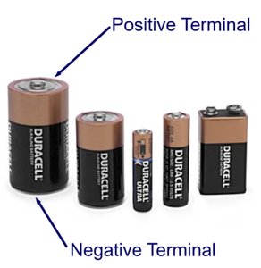
Terminals: Each battery has a positive and a negative terminal.
Voltage: The potential difference between the terminals is called the electromotive force (EMF).
Current Direction: Conventional current flows from the positive to the negative terminal.

Ohm's Law
Ohm's Law relates the current, voltage, and resistance in a circuit. It is a foundational principle for analyzing electric circuits.
Formula:
Solving for Current:
Solving for Resistance:
Resistance (R): Measured in ohms (Ω), it quantifies how much a material opposes the flow of current.
Ohmic vs. Non-Ohmic Materials: Ohmic materials have a linear relationship between current and voltage; non-ohmic materials do not.
Resistivity and Resistance
Resistance depends on the material's properties, length, and cross-sectional area. Resistivity (ρ) is a material-specific property.
Formula:
Variables: L = length (m), A = cross-sectional area (m²), ρ = resistivity (Ω·m)
Low Resistivity: Preferred for conductors (e.g., copper, silver).
Material | Resistivity (10-8 Ω·m) |
|---|---|
Silver | 1.59 |
Copper | 1.68 |
Gold | 2.44 |
Aluminum | 2.65 |
Tungsten | 5.60 |
Iron | 9.71 |
Platinum | 10.6 |
Mercury | 98 |
Nichrome | 100 |
Electrical Power
Power in an electric circuit is the rate at which energy is transferred or converted. It can be calculated using current and voltage or resistance.
Formula:
Alternate Forms: and
Unit: Watt (W), where 1 W = 1 J/s

Series and Parallel Circuits
Resistors can be connected in series or parallel, affecting the total (equivalent) resistance and current distribution.
Series Circuits
Current: Same through all components.
Voltage: Divided among components.
Equivalent Resistance:
Parallel Circuits
Voltage: Same across all branches.
Current: Divided among branches.
Equivalent Resistance:
Measurement: Voltmeters and Ammeters
Measuring devices are used to determine current and voltage in circuits.
Voltmeter: Measures voltage; connected in parallel; has high resistance.
Ammeter: Measures current; connected in series; has low resistance.
Multimeter: Can measure voltage, current, and resistance.
Electromotive Force (EMF) and Terminal Voltage
Batteries have an internal resistance, which affects the terminal voltage when a current is drawn.
EMF (ε): The maximum potential difference when no current flows.
Terminal Voltage (VT): The voltage across the battery's terminals when current flows.
Formula: (where r = internal resistance, I = current)
Equivalent Resistance in Circuits:
Example Problems and Applications
Calculating Current: Given charge and time, use .
Finding Resistance: Use or .
Power Dissipation: Use , , or as appropriate.
Series/Parallel Analysis: Reduce complex circuits to equivalent resistances for easier analysis.
Summary Table: Key Equations
Quantity | Equation | Units |
|---|---|---|
Current (I) | A (C/s) | |
Ohm's Law | V (volts) | |
Resistance (R) | Ω (ohms) | |
Power (P) | W (watts) | |
Power (alt.) | or | W (watts) |
Series Resistance | Ω (ohms) | |
Parallel Resistance | Ω (ohms) | |
Terminal Voltage | V (volts) |
Additional info: These notes are based on a comprehensive set of slides and problems covering the core concepts of electric current, resistance, Ohm's Law, power, and circuit analysis, including both series and parallel configurations, as well as practical measurement techniques and the effects of internal resistance in batteries.
