 Back
BackElectric Current, Circuits, and Resistance: Study Notes
Study Guide - Smart Notes
 Tailored notes based on your materials, expanded with key definitions, examples, and context.
Electric Current and Circuits
Introduction to Electric Current
Electric current is the flow of electric charge through a conductor, typically measured in amperes (A). In metallic conductors, this charge is carried by electrons, while in other media, such as electrolytes, it may be carried by ions. Understanding electric current is fundamental to analyzing electric circuits and their behavior.
Definition: Electric current (I) is the rate at which charge (q) flows through a cross-section of a conductor over time (t).
Formula:
Unit: The standard unit for electric current is the ampere (A), where .
Example: If 3 C of charge flows through a wire in 2 s, then .
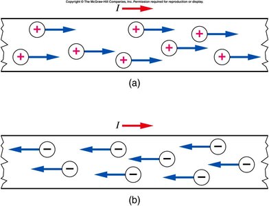
Conventional Current vs. Electron Current
There are two conventions for describing the direction of current in a circuit:
Conventional Current: Defined as the direction positive charges would flow (from the positive to the negative terminal).
Electron Current: In metals, electrons (negative charges) move from the negative to the positive terminal, which is opposite to the conventional current direction.
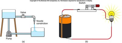
Analogy: Water Flow and Electric Circuits
Electric circuits can be understood using the analogy of water flowing through pipes:
The battery acts like a pump that drives the flow.
Electric charge is analogous to water.
Wires are like pipes that carry the flow.
The filament or resistor is like a nozzle or constriction in the pipe.
The switch is like a valve that opens or closes the flow.
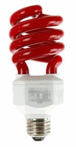
Fluorescent Light Bulbs and Gas Discharge
A fluorescent light bulb produces light by passing an electric current through a gas (usually argon and mercury vapor). The mercury atoms emit ultraviolet radiation, which excites a phosphor coating inside the tube, resulting in visible light. This is an example of a gas discharge lamp, where ultraviolet light is converted to visible light through fluorescence.
Current in Circuits
What Does a Bulb 'Use Up'?
When a bulb is connected in a circuit, it does not consume or destroy electrons. Instead, the bulb converts the chemical energy from the battery into light and heat energy. The number of electrons entering and leaving the bulb remains the same; only their energy changes.
Key Point: The bulb uses up energy, not current or electrons.
Conservation: Electrons are not destroyed or accumulated in the bulb.
Kirchhoff's Current Law (Current Node Rule)
At any junction (node) in an electric circuit, the total current entering the node is equal to the total current leaving the node. This is a statement of conservation of charge.
Formula:
Application: Used to analyze complex circuits with multiple branches.
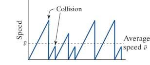
Electric Field in a Circuit
Electrons move through a conductor by 'surfing' through the lattice of atoms. They are accelerated by the electric field but lose energy due to collisions with lattice defects and vibrations. A continuous electric field is needed to keep the electrons moving.
Resistance and Ohm's Law
Ohm's Law
Ohm's Law relates the current flowing through a conductor to the voltage across it and its resistance. It is a fundamental law for analyzing electric circuits.
Formula:
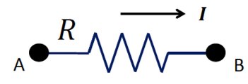
Resistance (R): The property of a material that resists the flow of electric current, measured in ohms (Ω).
Direction: Current flows from higher to lower potential (except inside a battery).
Energy Dissipation: Resistors convert electrical energy into heat due to friction-like effects.
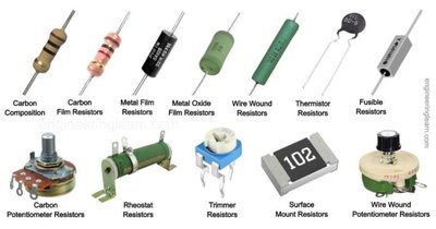
Properties of Resistors
The resistance of a conductor depends on its material, length, and cross-sectional area:
Formula:
Where: is the resistivity of the material, is the length, and is the cross-sectional area.
Tip: The Greek letter (rho) is used for resistivity.
Wires, Switches, and Batteries in Circuits
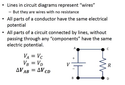
Wires
In ideal circuit diagrams, wires are assumed to have zero resistance. All points along a wire are at the same electric potential, and the current is the same throughout.
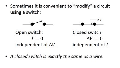
Switches
Switches are used to open or close a circuit. An open switch prevents current flow, while a closed switch allows current to flow as if it were a wire.
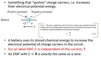
Batteries and Electromotive Force (EMF)
A battery provides the electromotive force (EMF) that drives current through a circuit. The EMF is the potential difference created by the battery, often denoted as or .
Formula:
Key Point: For an ideal battery, EMF is independent of the current.
Analyzing Simple Circuits
Series Circuits
When resistors are connected in series, the same current flows through each resistor. The total resistance is the sum of individual resistances.
Formula:
Current:
Voltage Divider
A voltage divider is a simple circuit that uses resistors in series to produce a fraction of the input voltage at a specific point.
Formula:
Parallel Circuits
When resistors are connected in parallel, the voltage across each resistor is the same, but the total current is divided among the branches. The reciprocal of the total resistance is the sum of the reciprocals of individual resistances.
Formula:
General Rules for Series and Parallel Resistors
Configuration | Equivalent Resistance |
|---|---|
Series | |
Parallel |
Summary Table: Key Concepts
Concept | Formula/Definition |
|---|---|
Current | |
Ohm's Law | |
Resistance | |
Series Resistance | |
Parallel Resistance | |
Kirchhoff's Current Law |
