 Back
BackElectric Current, Circuits, and Resistance: Study Notes
Study Guide - Smart Notes
 Tailored notes based on your materials, expanded with key definitions, examples, and context.
Electric Current and Circuits
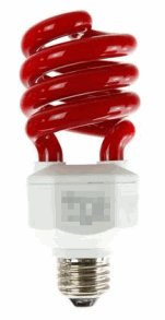
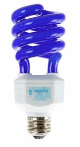
Fluorescent Light Bulbs and Gas Discharge
Fluorescent light bulbs operate by passing an electric current through a gas, typically a mixture of argon and mercury vapor. The electric current excites the mercury atoms, causing them to emit ultraviolet radiation. This ultraviolet light then excites a phosphor coating on the inside of the tube, resulting in visible light. This process is an example of a gas discharge lamp, where the emitted ultraviolet light is converted to visible light through fluorescence.
Key Point: Electric current is necessary to excite the gas and produce light.
Application: Used in energy-efficient lighting.
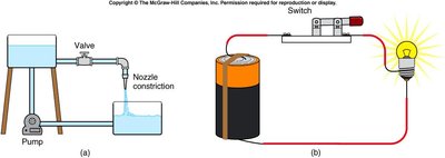
Water Flow Analogy for Electric Circuits
Water flowing in a pipe is analogous to electric current flowing in a circuit. The battery acts as a pump, electric charge is like water, connecting wires are like pipes, the filament is like a nozzle, and the switch is like a valve. This analogy helps visualize how current moves through a circuit and how components control the flow.
Key Point: Each component in the circuit has a direct analogy in fluid systems.
Example: Opening a valve (switch) allows water (current) to flow.
Electric Current
Definition and Units
Electric current is the flow of electric charge through a conductor. The standard unit for electric current is the ampere (A), defined as one coulomb (C) of charge passing through a cross-section per second (s).
Formula:
Unit:
Example: If 3 C of charge flows through a wire in 2 s, then .
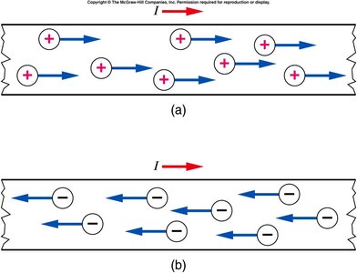
Conventional Current vs. Electron Current
Conventional current is defined as the direction in which positive charges would flow, while electron current is the actual flow of negatively charged electrons in a metal wire. Despite electrons moving from the negative to the positive terminal, conventional current is considered to flow from positive to negative.
Key Point: Positive charges moving right are equivalent to negative charges moving left.
Application: Circuit diagrams use conventional current direction.
Energy in Circuits
What Does a Bulb Use Up?
A bulb does not consume current by destroying electrons or accumulating them. Instead, the bulb uses the chemical energy from the battery and converts it into light and heat energy. Electrons are not destroyed; they continue to flow through the circuit.
Key Point: Energy, not charge, is consumed in the circuit.
Example: The battery's chemical energy is converted to light and heat.
Kirchhoff's Current Law (Current Node Rule)
Current Conservation at Nodes
Kirchhoff's Current Law states that the total current entering a node (junction) in a circuit equals the total current leaving the node. This is a consequence of charge conservation.
Formula:
Application: Used to analyze complex circuits.
Electric Field in Circuits
Electron Motion and Collisions
Electrons move through a lattice in a conductor, occasionally colliding with lattice defects or deformations. An electric field is required throughout the wire to re-accelerate electrons after collisions, maintaining the flow of current.
Key Point: Collisions cause energy loss, leading to resistance.
Application: Explains why resistors heat up.

Resistors and Ohm's Law
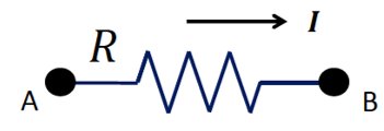
Ohm's Law
Ohm's Law relates the current (I) through a resistor to the voltage (V) across it and its resistance (R):
Formula:
Resistance: The ability of a resistor to resist electrical current, causing energy dissipation as heat.
Application: Used to calculate current, voltage, or resistance in circuits.
Properties of Resistors
The electrical resistance R of a circuit element depends on its length (L), cross-sectional area (A), and the resistivity (\(\rho\)) of the material:
Formula:
Resistivity: \(\rho\) is a material property; do not confuse with density.
Application: Used to design resistors for specific purposes.
Wires and Components in Circuits
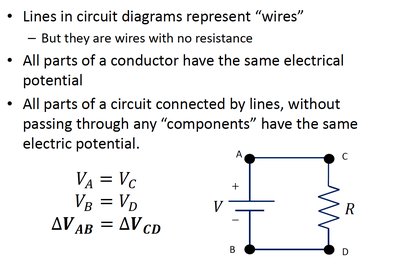
Ideal Wires
In circuit diagrams, wires are considered ideal, meaning they have no resistance. All points along an ideal wire are at the same electrical potential, and the current is the same throughout.
Key Point: Wires simply connect circuit elements; they do not affect current or voltage.
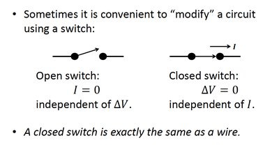
Switches
Switches are used to open or close circuits. An open switch prevents current flow, while a closed switch allows current to flow as if it were a wire.
Open Switch: , independent of
Closed Switch: , independent of
Batteries and Electromotive Force (EMF)
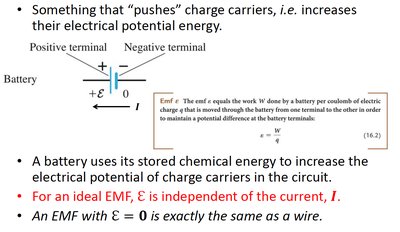
Battery as a Source of EMF
A battery uses stored chemical energy to increase the electrical potential of charge carriers in a circuit. The electromotive force (EMF) is the potential difference created by an ideal battery and is independent of the current.
Formula:
Application: EMF is often denoted as (battery voltage).
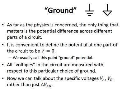
Ground in Circuits
Defining Ground Potential
In circuit analysis, it is convenient to define the potential at one part of the circuit as zero, called "ground". All voltages in the circuit are measured with respect to this ground potential.
Key Point: Ground simplifies voltage calculations.
Resistors in Series and Parallel
Resistors in Series
When resistors are connected in series, the total resistance is the sum of the individual resistances. The same current flows through each resistor.
Formula:
Current:
Resistors in Parallel
When resistors are connected in parallel, the equivalent resistance is given by the reciprocal sum of the individual resistances. The voltage across each resistor is the same, but the current divides among the branches.
Formula:
Current:
Voltage Divider
A voltage divider is a simple circuit with two resistors in series, used to produce a fraction of the input voltage. The voltage at a point between the resistors is determined by their relative values.
Formula:
Summary Table: Series vs. Parallel Resistors
Configuration | Equivalent Resistance | Current | Voltage |
|---|---|---|---|
Series | Same through all | Divides across resistors | |
Parallel | Divides among branches | Same across all |
Additional info: Academic context was added to clarify the analogy between water flow and electric circuits, the physical meaning of resistance, and the practical use of voltage dividers.
