 Back
BackElectromagnetic Induction and Faraday’s Law: Motional EMF, Magnetic Flux, and Lenz’s Law Ch 30
Study Guide - Smart Notes
 Tailored notes based on your materials, expanded with key definitions, examples, and context.
Electromagnetic Induction
Introduction to Electromagnetic Induction
Electromagnetic induction is the process by which a changing magnetic field induces an electromotive force (EMF) and, consequently, an electric current in a conductor. This phenomenon is fundamental to the operation of generators, transformers, and many other electrical devices.
Electric currents create magnetic fields.
Magnetic fields exert forces on moving charges.
A changing magnetic field can induce a current in a circuit (Faraday’s discovery).
Faraday’s Law of Induction
Faraday’s Law quantitatively describes how a time-varying magnetic flux through a circuit induces an EMF in the circuit.
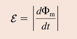
Faraday’s Law:
is the induced EMF (in volts).
is the magnetic flux through the circuit (in webers, Wb).
The negative sign indicates the direction of the induced EMF opposes the change in flux (Lenz’s Law).
Demonstration: Two-Coil Induction
When a current in one coil is switched on or off, the changing magnetic field induces a current in a nearby coil only while the magnetic field is changing.
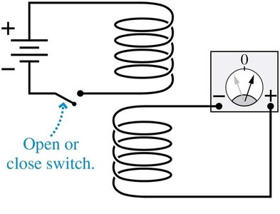
Key Point: Current is induced in the second coil only when the magnetic field is changing (i.e., while the switch is being opened or closed).
Motional EMF
Concept of Motional EMF
Motional EMF is generated when a conductor moves through a magnetic field, causing charge separation due to the Lorentz force.
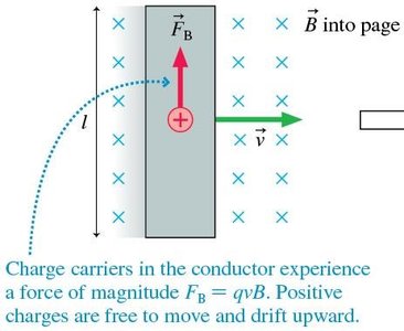
Charge carriers in the conductor experience a force perpendicular to both their velocity and the magnetic field.
Positive charges drift upward, creating a potential difference across the bar.
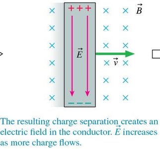
This separation creates an electric field inside the conductor, which increases as more charge accumulates.
Induced Current in a Moving Conductor
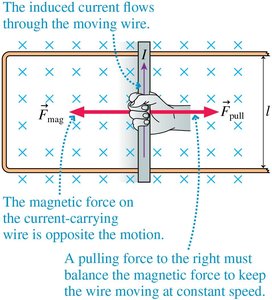
When the moving bar is part of a closed circuit, the separated charges flow, creating an induced current.
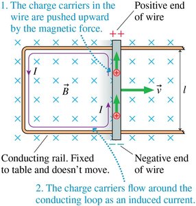
The direction of the induced current is determined by the direction of the magnetic force on the charge carriers.
The magnitude of the induced current is given by:
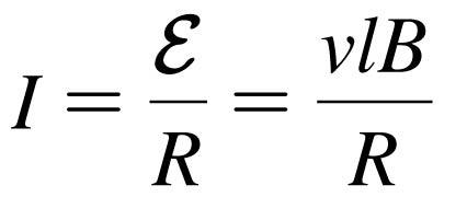
= velocity of the bar, = length of the bar, = magnetic field strength, = resistance of the circuit.
Forces and Power in Motional EMF
The induced current interacts with the magnetic field, producing a force that opposes the motion of the conductor (Lenz’s Law). To keep the bar moving at constant speed, an external force must be applied.
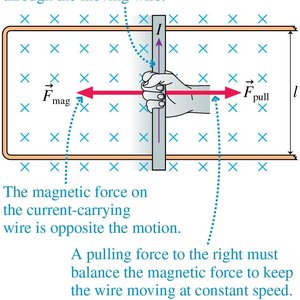
The magnetic force on the wire is and acts opposite to the direction of motion.
The pulling force must balance this magnetic force to maintain constant velocity.
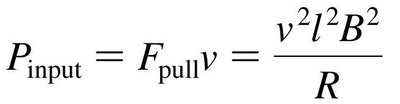
The power required to pull the bar at constant speed is:
Magnetic Flux
Definition of Magnetic Flux
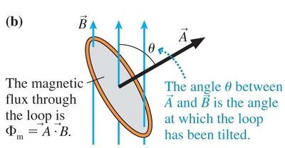
Magnetic flux () quantifies the total magnetic field passing through a given area. It is a key concept in understanding electromagnetic induction.
For a uniform magnetic field and a flat surface, magnetic flux is:
= area of the loop, = magnetic field strength, = angle between the area vector and the magnetic field.
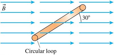
Examples of Calculating Magnetic Flux
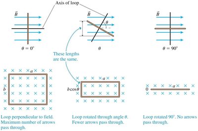
When the loop is perpendicular to the field (), the flux is maximized. As the loop rotates, the flux decreases, becoming zero when the loop is parallel to the field ().
Lenz’s Law
Statement and Application of Lenz’s Law
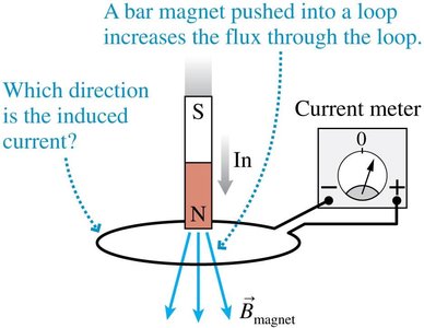
Lenz’s Law determines the direction of the induced current in a closed loop. The induced current always flows in a direction that opposes the change in magnetic flux through the loop.
If the magnetic flux through a loop increases, the induced current creates a magnetic field opposing the increase.
If the flux decreases, the induced current creates a field that tries to maintain the original flux.
Example: Pushing a bar magnet into a loop increases the flux; the induced current flows to oppose this increase.
Faraday’s Law: General Formulation
Mathematical Expression
Faraday’s Law in its general form relates the induced EMF to the rate of change of magnetic flux:
The negative sign reflects Lenz’s Law: the induced EMF opposes the change in flux.
Application: Motional EMF as a Special Case
When a conductor moves in a constant magnetic field, the change in area (and thus flux) as the bar moves leads to an induced EMF:
This is consistent with the general Faraday’s Law, as the change in area per unit time is .
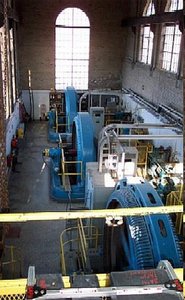
Electromagnetic Induction in Generators
Alternating Current (AC) Generator
Generators convert mechanical energy into electrical energy by rotating a coil in a magnetic field, inducing an alternating EMF according to Faraday’s Law.

The induced EMF varies sinusoidally with time as the coil rotates.
The general expression for the induced EMF in a coil with turns is:
Summary Table: Key Equations and Concepts
Concept | Equation | Description |
|---|---|---|
Faraday’s Law | Induced EMF equals the negative rate of change of magnetic flux. | |
Motional EMF | EMF induced by a conductor of length moving at speed in field . | |
Induced Current | Current induced in a closed circuit of resistance . | |
Magnetic Flux | Flux through area at angle to field . | |
Power Input | Power required to move the conductor at constant speed. |
Additional info: These notes cover the core principles of electromagnetic induction, including Faraday’s Law, motional EMF, magnetic flux, and Lenz’s Law, with applications to generators and practical circuits. The included images directly illustrate the physical processes and equations described.
