 Back
Electromagnetic Induction and Faraday’s Law: Study Notes
Study Guide - Smart Notes
 Tailored notes based on your materials, expanded with key definitions, examples, and context.
Electromagnetic Induction and Faraday’s Law
Magnetic Flux
Magnetic flux is a measure of the quantity of magnetism, taking into account the strength and the extent of a magnetic field. It is a fundamental concept in electromagnetism, especially in understanding how changing magnetic fields induce electric currents.
Definition: Magnetic flux (\( \Phi \)) is defined as the product of the magnetic field (\( B \)), the area (\( A \)) through which the field lines pass, and the cosine of the angle (\( \theta \)) between the field and the area vector.
Formula: $\Phi = BA \cos \theta$
SI Unit: Weber (Wb), where 1 Wb = 1 T·m2
Key Variables: B: Magnetic field, A: Area vector, \theta: Angle between B and A
Example: For a wire loop of radius 0.50 m in a 0.60 T field:
(a) Perpendicular (\( \theta = 0^\circ \)): $\Phi = BA$
(b) Parallel (\( \theta = 90^\circ \)): $\Phi = 0$
(c) At 30°: $\Phi = BA \cos 30^\circ$
Changing Magnetic Flux
Magnetic flux can be changed by altering the area, the angle, or the magnetic field itself. These changes are essential for inducing an electromotive force (emf).
Change the area (A): Adjusting the size of the loop.
Change the angle (\( \theta \)): Rotating the loop relative to the field.
Change the field (B): Varying the strength of the magnetic field.
Faraday’s Law of Induction
Faraday’s Law quantifies the induced emf resulting from a changing magnetic flux. The induced emf can drive a current in a closed circuit.
Formula: $E = -N \frac{d\Phi}{dt}$
N: Number of turns in the coil
\( \frac{d\Phi}{dt} \): Rate of change of magnetic flux
The negative sign indicates the direction of the induced emf opposes the change in flux (Lenz’s Law).
Lenz’s Law
Lenz’s Law states that the direction of the induced emf and current is such that it opposes the change in magnetic flux that produced it.
If flux is increasing, the induced current creates a magnetic field opposing the increase.
If flux is decreasing, the induced current creates a magnetic field supporting the original field.
Applications and Problem Solving
To solve problems involving electromagnetic induction:
Determine the direction of the external magnetic field.
Assess whether the flux is increasing or decreasing.
Choose the current direction to oppose the change in flux.
Example: A coil of 200 turns, resistance 2.00 Ω, area 0.18 m × 0.18 m, magnetic field changes from 0 to 0.5 T in 0.8 s at 35°.
Calculate induced emf: $E = -N \frac{d\Phi}{dt}$
Calculate current: $I = \frac{E}{R}$
Motional emf
Motional emf is generated when a conductor moves through a magnetic field, causing a separation of charges and creating a potential difference.
Formula: $E = BLv$
v: Velocity of the conductor
L: Length of the conductor in the field
Example: Driving a car at 75 mph in Earth’s magnetic field (5.0×10⁻⁵ T), width 1.5 m: Calculate induced emf.
Eddy Currents
Eddy currents are loops of electrical current induced within conductors by a changing magnetic field. They can cause energy dissipation as heat and are used in applications like electromagnetic braking.
Do not require wires; occur in metal plates, tubes, etc.
Result in forces that oppose motion and cause energy loss.
Electric Generators and Motors
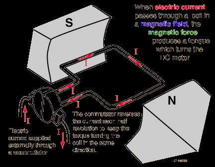
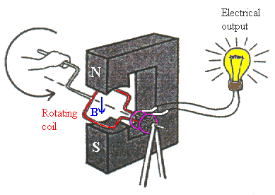
Electric generators convert mechanical energy into electrical energy by rotating a coil in a magnetic field, while electric motors convert electrical energy into mechanical energy by running a current through a coil in a magnetic field.
Generator: Rotating coil induces current.
Motor: Current causes coil to rotate.
Countertorque: Induced current in generator creates torque opposing rotation.
Counter emf: Motor acts as generator when spinning, reducing net current.
Self and Mutual Inductance
Inductance is the property of a circuit that opposes changes in current due to the creation of a magnetic field.
Self Inductance (L): $L = \frac{N d\Phi}{dI}$
Voltage across inductor: $E = -L \frac{dI}{dt}$
Mutual Inductance (M): $E_2 = -M \frac{dI_1}{dt}$
SI Unit: Henry (H)
Energy in an Inductor
Inductors store energy in their magnetic fields. The energy stored is proportional to the square of the current.
Formula: $U = \frac{1}{2} L I^2$
Energy density: $u = \frac{1}{2} \frac{B^2}{\mu_0}$
Transformers
Transformers are devices that transfer electrical energy between two or more coils through electromagnetic induction. They are used to increase or decrease voltage in AC circuits.
Works only with AC.
Voltage ratio: $\frac{V_s}{V_p} = \frac{N_s}{N_p}$
Current ratio: $\frac{I_p}{I_s} = \frac{N_s}{N_p}$
Power conservation: $P_1 = P_2$
Capacitors and Inductors in AC Circuits
Capacitors and inductors behave differently in AC circuits compared to DC circuits, affecting current and voltage phase relationships.
Capacitive Reactance: $X_C = \frac{1}{2\pi f C}$
Inductive Reactance: $X_L = 2\pi f L$
Capacitors act as open circuits at low frequency, closed at high frequency.
Inductors act as closed circuits at low frequency, open at high frequency.
Example: An 8.00 µF capacitor in a 150 V, 60 Hz AC circuit: Calculate $X_C$ and rms current.
Additional info: These notes cover the main concepts, formulas, and applications of electromagnetic induction, Faraday’s Law, Lenz’s Law, motional emf, eddy currents, generators, motors, inductance, transformers, and AC circuit behavior, as relevant to a college-level Physics with Calculus course.
