 Back
BackLecture 13
Study Guide - Smart Notes
 Tailored notes based on your materials, expanded with key definitions, examples, and context.
Magnetic Fields Produced by Currents
Solenoids and Magnetic Field Calculation
A solenoid is a coil of wire consisting of many loops, which produces a nearly uniform magnetic field inside when a current flows through it. The strength of the magnetic field inside a long solenoid depends on the number of turns per unit length (n) and the current (I) flowing through the wire.
Formula for Magnetic Field in a Solenoid:
Where: is the permeability of free space ( T·m/A), is the number of turns per meter, and is the current in amperes.
Field Lines: The magnetic field lines inside a solenoid resemble those of a bar magnet, with distinct North and South poles.
Right-Hand Rule (RHR): Used to determine the direction of the magnetic field inside the solenoid.
Example Calculation: For a solenoid 0.25 m long with 5000 turns and a current of 3.5 A: turns/m, T.
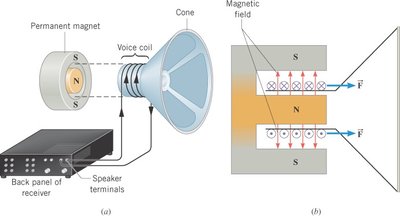
The Force on a Current in a Magnetic Field
Magnetic Force and Applications
When a current-carrying wire is placed in a magnetic field, it experiences a force. This principle is used in devices such as loudspeakers, where the force on the voice coil causes the cone to vibrate and produce sound.
Formula:
Where: is the current, is the length of wire in the field, is the magnetic field strength, and is the angle between the wire and the field.
Example: A voice coil with 55 turns, diameter 0.025 m, in a 0.10 T field, carrying 2.0 A: N.
Acceleration: , where is the mass of the coil and cone.
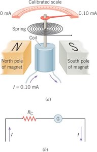
The Torque on a Current-Carrying Coil
Rotational Effects and Galvanometers
A current-carrying loop in a magnetic field experiences a torque, which tends to align the loop's normal with the magnetic field. This effect is used in devices such as galvanometers and DC motors.
Torque Formula:
Where: is the number of turns, is the current, is the area, is the magnetic field, and is the angle between the normal and the field.
Galvanometer: Measures current by balancing magnetic torque with spring torque ().
DC Motor: Uses a split-ring commutator to maintain rotation by reversing current direction.
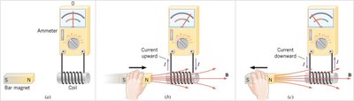
Electromagnetic Induction
Induced EMF and Current
Electromagnetic induction occurs when a changing magnetic field induces an electromotive force (emf) and current in a conductor. This is the basis for generators and many electrical devices.
Induced EMF: Produced by changing the magnetic field, area, or orientation of a coil.
Complete Circuit: Both emf and current are induced if the circuit is closed.
Electromagnetic Induction: The process of generating emf with a magnetic field.
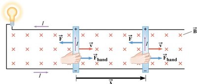
Motional EMF
EMF Induced in a Moving Conductor
When a conductor moves through a magnetic field, charges within the conductor experience a force, resulting in a separation of charges and an induced emf known as motional emf.
Formula:
Where: is the velocity, is the magnetic field, and is the length of the conductor.
Example: A rod moving at 5.0 m/s perpendicular to a 0.80 T field, length 1.6 m: V.
Current: , where is resistance.
Power:
Energy:
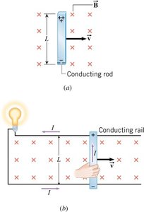
Electrical Energy and Conservation
To keep the rod moving at constant velocity, an external force must balance the magnetic force. The work done by this force is converted into electrical energy.
Force:
Work:
Conservation of Energy: The energy supplied by the hand equals the energy used by the bulb.
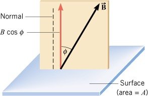
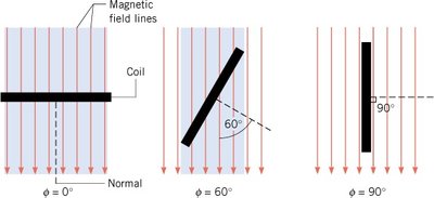
Magnetic Flux
Definition and Calculation
Magnetic flux () quantifies the amount of magnetic field passing through a given area. It is a key concept in understanding electromagnetic induction.
Formula:
Units: Tesla·meter2 (T·m2) = Weber (Wb)
Dependence: Flux depends on the angle between the field and the area.
Example: For T, m2, : Wb, Wb, Wb.
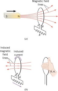
Faraday’s Law of Electromagnetic Induction
Law and Applications
Faraday’s Law states that the average emf induced in a coil is proportional to the rate of change of magnetic flux through the coil. The direction of the induced emf opposes the change in flux, as described by Lenz’s Law.
Formula:
Where: is the number of turns, is the change in flux, is the time interval.
Lenz’s Law: The induced emf creates a current whose magnetic field opposes the original change in flux.
Example: A coil with 20 turns, area 0.0015 m2, changes from 0.050 T to 0.060 T in 0.10 s: V.
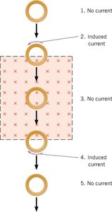
Lenz’s Law
Direction of Induced Current
Lenz’s Law provides a reasoning strategy for determining the direction of induced current:
1. Determine if the magnetic flux is increasing or decreasing.
2. Find the direction of the induced magnetic field to oppose the change.
3. Use the right-hand rule to determine the direction of the induced current.
Summary Table: Key Formulas and Concepts
Concept | Formula | Units |
|---|---|---|
Solenoid Magnetic Field | Tesla (T) | |
Magnetic Force | Newton (N) | |
Motional EMF | Volt (V) | |
Magnetic Flux | Weber (Wb) | |
Faraday's Law | Volt (V) | |
Torque on Coil | Newton-meter (N·m) |
