 Back
BackElectromagnetic Induction: Faraday’s Law, Lenz’s Law, and Applications
Study Guide - Smart Notes
 Tailored notes based on your materials, expanded with key definitions, examples, and context.
Electromagnetic Induction
Introduction to Electromagnetic Induction
Electromagnetic induction is the process by which a changing magnetic field within a closed loop induces an electromotive force (emf) and, if the circuit is closed, an electric current. This phenomenon is fundamental to the operation of generators, transformers, and many other electrical devices.
Induced emf: The voltage generated by a changing magnetic environment.
Induced current: The current resulting from the induced emf in a closed circuit.
Key Principle: A current is only induced when the magnetic flux through a circuit changes with time.
Induced EMF and Induced Current
Mechanisms of Induction
There are several ways to induce an emf in a circuit:
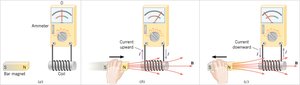
Moving a magnet relative to a coil
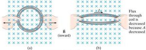
Changing the area of a coil in a constant magnetic field
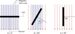
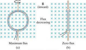
Altering the orientation (angle) of a coil with respect to the magnetic field
In all cases, it is the change in magnetic flux that produces the emf.
Magnetic Flux
Definition and Calculation
Magnetic flux (ΦB) quantifies the total magnetic field passing through a given area. It is defined as:
B: Magnetic flux density (T, tesla)
A: Area of the loop (m2)
θ: Angle between the magnetic field and the normal to the surface
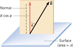
The flux is maximum when the field is perpendicular to the surface (θ = 0°) and zero when parallel (θ = 90°).
Faraday’s Law of Electromagnetic Induction
Statement and Mathematical Formulation
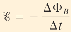
Faraday’s Law states that the induced emf in a circuit is equal to the negative rate of change of magnetic flux through the circuit:
For a coil with N turns:
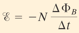
The negative sign indicates the direction of the induced emf (Lenz’s Law).
Magnetic flux can change by varying:
The magnetic field strength (B)
The area of the loop (A)
The orientation angle (θ)
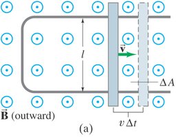
Motional EMF
EMF Induced by a Moving Conductor
When a conductor moves through a magnetic field, an emf is induced across its ends. This is called motional emf and is given by:
B: Magnetic field strength (T)
l: Length of the conductor within the field (m)
v: Velocity of the conductor (m/s)
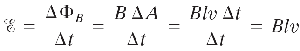
The direction of the induced emf can be determined using the right-hand rule for positive charges (or left-hand for electrons).
Lenz’s Law
Direction of Induced EMF and Current
Lenz’s Law states that the direction of the induced emf and current is such that it opposes the change in magnetic flux that produced it. This is a consequence of the conservation of energy and is reflected in the negative sign in Faraday’s Law.
If the magnetic flux through a loop increases, the induced current creates a magnetic field opposing the increase.
If the flux decreases, the induced current creates a field that tries to maintain the original flux.


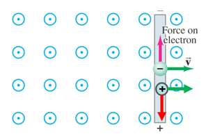
Right-Hand Rule for Coils
To determine the direction of the induced magnetic field in a coil, wrap your right-hand fingers in the direction of the current; your thumb points in the direction of the induced magnetic field (north pole of the coil).
Applications and Examples
Example: Induced EMF in a Changing Magnetic Field
A coil of wire consists of 20 turns, each with an area of 0.0015 m2. A magnetic field perpendicular to the surface increases from 0.050 T to 0.060 T in 0.10 s. The average induced emf is calculated using Faraday’s Law.
Example: Motional EMF in a Moving Rod
A rod of length 1.6 m moves at 5.0 m/s perpendicular to a 0.80 T magnetic field. The emf produced is:
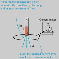
Example: Lenz’s Law with a Moving Magnet
When a bar magnet is pushed into a loop, the induced current flows in a direction that opposes the increase in magnetic flux. When the magnet is pulled away, the current reverses to oppose the decrease in flux.

Summary Table: Electromagnetic Induction
Cause of Flux Change | Induced Effect | Direction (Lenz's Law) |
|---|---|---|
Increase in B, A, or cosθ | Induced emf and current | Opposes increase (creates opposing field) |
Decrease in B, A, or cosθ | Induced emf and current | Opposes decrease (reinforces original field) |
No change in flux | No induced emf or current | — |
Practice Problems and Solutions
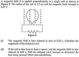
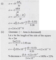
Exercise 1
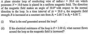
Exercise 2
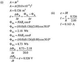
Additional info: These exercises reinforce the calculation of induced emf and current using Faraday’s Law and the concept of changing magnetic flux.
