 Back
BackElectromagnetic Induction: Principles, Laws, and Applications
Study Guide - Smart Notes
 Tailored notes based on your materials, expanded with key definitions, examples, and context.
Electromagnetic Induction
Introduction to Electromagnetic Induction
Electromagnetic induction is the process by which a changing magnetic field creates an electric field, resulting in a potential difference and current in a conductor. This phenomenon is fundamental to the operation of generators, transformers, and many other electrical devices. - Key Point 1: Inserting a magnet into a coil induces a current; the amount of current depends on both the strength of the magnetic field and the speed of insertion. - Key Point 2: No batteries or external power sources are needed; the current is generated solely by the changing magnetic field. 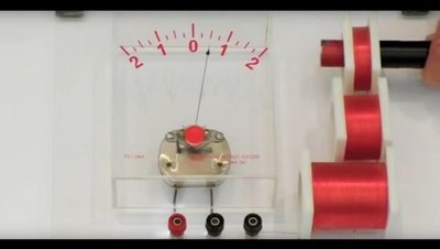
Experimental Observations of Induced Current
The induction of current can be observed using a coil and a galvanometer. Several experiments demonstrate the conditions under which current is induced: - Motionless Magnet: No current is observed when the magnet is stationary. 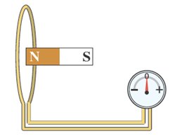 - Magnet Moved Toward Coil: Current flows while the magnet is moving toward the coil.
 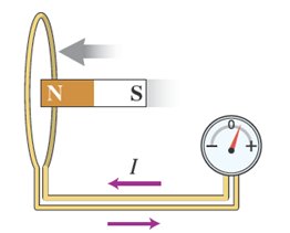 - Magnet Moved Away from Coil: Current flows in the opposite direction when the magnet is moved away from the coil.
 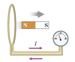 - Magnet Rotated: Turning the magnet induces a current.
 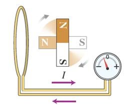 - Changing Coil Area: Reducing the coil's area induces a current.
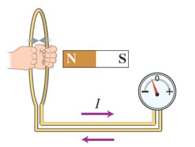
Magnetic Flux (\(\Phi_m\))
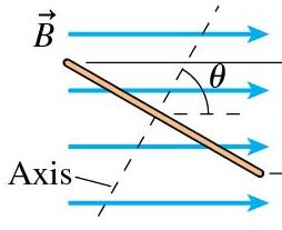
Magnetic flux is a measure of the number of magnetic field lines passing through a loop or coil. It is a key concept in understanding electromagnetic induction. - Definition: Magnetic flux quantifies the total magnetic field passing through a given area. - Formula: For a single loop, magnetic flux is given by: where: = magnetic field strength, = area enclosed by the loop, = angle between the magnetic field and the area vector (perpendicular to the loop). - SI Unit: Weber (Wb), equivalent to Tesla·meter2 (T·m2). - Maximum Flux: When (field perpendicular to loop). - Zero Flux: When (field parallel to loop). 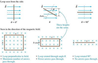
Lenz's Law
Lenz's law describes the direction of the induced current in a loop due to changing magnetic flux. - Key Point 1: An induced current appears only if the magnetic flux through the loop is changing. - Key Point 2: The direction of the induced current is such that the induced magnetic field opposes the change in flux. - Flux Changes: Flux can change if the magnetic field strength changes, the loop's area or orientation changes, or the loop moves into/out of a magnetic field. 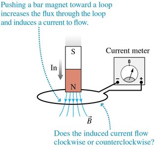
Warm-Up: Comparing Magnetic Flux
The magnetic flux through a loop depends on both the strength of the magnetic field and the area of the loop. - Example: Two loops in different fields or with different areas may have the same or different flux depending on these factors. 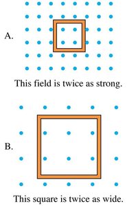
Using Lenz's Law: Step-by-Step
To determine the direction of induced current: 1. Identify the direction of the external magnetic field. 2. Determine whether the flux is increasing, decreasing, or constant. 3. If flux is changing, the induced magnetic field opposes the change: - Increasing flux: induced field opposes external field. - Decreasing flux: induced field aligns with external field. 4. Use the right-hand rule to determine the direction of induced current.
Guided Example: Moving Loop Near Current-Carrying Wire
When a loop moves toward a current-carrying wire, the magnetic flux through the loop changes, inducing a current. - Key Point: The direction of induced current depends on whether the flux is increasing or decreasing and is determined by Lenz's law. 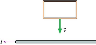

Faraday's Law of Induction
Faraday's law quantifies the induced voltage (emf) in a loop due to changing magnetic flux. - For one loop: - For a coil with turns: - Induced Current: The magnitude of induced current is given by Ohm's law: , where is resistance. 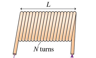
Example: Calculating Induced Current
A loop of wire with radius 5 cm and resistance 0.2 Ω is placed in a region where the magnetic field increases from 0 T to 1.8 T in 3 seconds. - Step 1: Calculate area: - Step 2: Calculate change in flux: - Step 3: Calculate induced emf: - Step 4: Calculate induced current:
Graphs of Induced Current vs. Time
The induced current in a loop varies with the rate of change of the magnetic field. - Key Point: When the magnetic field is constant, no current is induced. - Key Point: When the field increases or decreases, current is induced, with direction determined by Lenz's law.
Motional EMF
Motional emf is generated when a conductor moves through a magnetic field, causing charge separation and an induced voltage. - Key Point 1: Charge carriers in a moving conductor experience a magnetic force, leading to separation and an internal electric field. - Key Point 2: The induced voltage (motional emf) is given by: where = speed, = length perpendicular to velocity, = magnetic field strength. 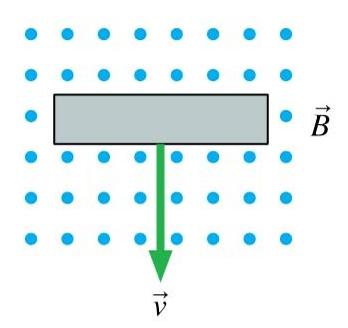
Application: Metal Bar on Conducting Rail
When a metal bar moves along a U-shaped conducting rail in a magnetic field, an induced current flows. - Key Point: The direction of induced current is determined by Lenz's law and the right-hand rule. 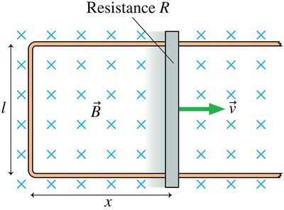
Summary Table: Key Concepts in Electromagnetic Induction
Concept | Definition | Formula | Key Points |
|---|---|---|---|
Magnetic Flux (\(\Phi_m\)) | Number of magnetic field lines through a loop | Depends on field strength, area, and angle | |
Lenz's Law | Direction of induced current opposes change in flux | N/A | Induced current only if flux changes |
Faraday's Law | Induced emf proportional to rate of change of flux | For coils: multiply by number of turns | |
Motional EMF | Voltage induced by moving conductor in field | Direction by right-hand rule |
Additional info: Academic context and step-by-step calculations were added to ensure completeness and clarity for exam preparation.
