 Back
BackElectrons as Charge Carriers and Interpreting V-I Graphs
Study Guide - Smart Notes
 Tailored notes based on your materials, expanded with key definitions, examples, and context.
Electrons as Charge Carriers
Introduction to Charge Carriers
Electric current in materials is due to the movement of charge carriers. In metals, these are electrons, while in semiconductors, both electrons and holes can act as charge carriers. Understanding the behavior of these carriers is fundamental to analyzing electrical conduction in different materials.
Conduction electrons in metals: In metals, some electrons are not bound to atoms and can move freely, forming a 'sea' of electrons responsible for electrical conduction.
Conduction electrons in semiconductors: In semiconductors, electrons can be excited from the valence band to the conduction band, leaving behind holes that also act as positive charge carriers.
Thermal Excitation and Doping
Thermal energy can excite electrons in semiconductors, increasing conductivity. Doping introduces impurities to enhance the number of charge carriers, creating n-type (extra electrons) or p-type (extra holes) semiconductors.
Thermal excitation: At higher temperatures, more electrons gain enough energy to jump into the conduction band.
Doping: Adding donor or acceptor atoms increases the number of free electrons or holes, respectively.
Electron Beams and Induced Currents
Electron beams are streams of electrons accelerated by electric fields, commonly used in cathode ray tubes. Induced currents arise when a changing magnetic field creates an electromotive force (EMF) in a conductor.
Interpreting and Using V-I Graphs
Understanding V-I Characteristics
The voltage-current (V-I) characteristic of a device shows how current varies with applied voltage. The shape of the V-I graph reveals the electrical behavior of the component.
Ohmic conductors: These obey Ohm's law, showing a straight-line V-I graph through the origin. The resistance is constant and given by the gradient.
Non-ohmic conductors: Devices like filament lamps and diodes do not have a constant resistance, resulting in curved V-I graphs.
Examples of V-I Graphs
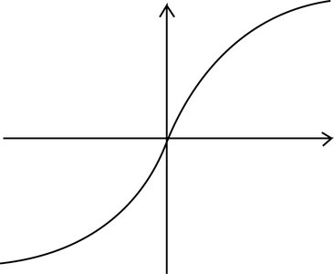
Filament lamp: The resistance increases with temperature, so the V-I graph curves, showing a decreasing gradient as current increases.
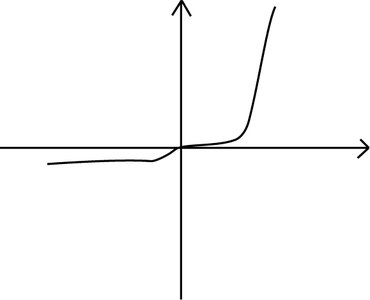
Semiconductor diode: The diode conducts significantly only after a threshold voltage (forward bias), and blocks current in reverse bias except for a small leakage.
Key Equations
Ohm's Law:
Resistance from V-I graph: (for a straight-line graph)
Applications and Analysis
V-I graphs are used to determine the resistance and behavior of electrical components under different conditions.
Understanding these graphs is essential for circuit analysis and for predicting how devices will respond to varying voltages.
Summary Table: V-I Characteristics of Common Components
Component | V-I Graph Shape | Behavior |
|---|---|---|
Ohmic Resistor | Straight line through origin | Constant resistance |
Filament Lamp | Curved, gradient decreases with I | Resistance increases with temperature |
Semiconductor Diode | Very low current until threshold, then sharp rise | Conducts in one direction only |
Practice and Application
Analyze V-I graphs to identify the type of component and its resistance at different points.
Apply Ohm's law and understand deviations from linearity as indicators of non-ohmic behavior.
Additional info: The included images of V-I graphs for the filament lamp and semiconductor diode directly illustrate the non-linear behavior discussed in the text, reinforcing the importance of graphical analysis in understanding electrical components.
