 Back
BackElectrostatics, Electric Potential, and Capacitance: Study Notes for Physics College Students
Study Guide - Smart Notes
 Tailored notes based on your materials, expanded with key definitions, examples, and context.
Electrostatics and Conductors
Electrostatic Equilibrium in Conductors
At electrostatic equilibrium, the electric field inside a conductor is zero. This principle is fundamental to understanding charge distribution and shielding effects in conductors.
Key Point 1: Excess charge resides on the surface of a conductor, and the electric field inside is zero.
Key Point 2: When a charged object is placed inside a conductor (such as a metal bucket), the inner and outer surfaces acquire charges to maintain equilibrium.
Example: If a positively charged ball (+q) is placed inside a neutral metal bucket without touching it, the inner surface acquires -q, and the outer surface acquires +q.
Additional info: This is a direct application of Gauss's Law, which states that the net electric flux through a closed surface is proportional to the net charge enclosed.
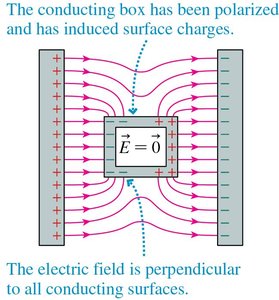
Faraday Cage and Shielding
A Faraday cage is a conducting enclosure that shields its interior from external electric fields. This is achieved by redistribution of charges on the surface, canceling the field inside.
Key Point 1: The electric field inside a Faraday cage is zero at equilibrium.
Key Point 2: Applications include protection from lightning strikes in aircraft and electrical safety demonstrations.
Example: The Boeing 787 uses conductive materials to reduce electric fields inside the aircraft during lightning strikes.

Electric Potential Energy
Potential Energy in Uniform Electric Fields
Electric potential energy is associated with the configuration of charged objects. In a uniform electric field, the potential energy of a charge q at distance s from the negative plate is:
Formula:
Key Point 1: Positive charges lose potential energy as they move toward the negative plate; negative charges gain potential energy.
Example: An electron released from rest in a parallel-plate capacitor accelerates toward the positive plate, converting potential energy to kinetic energy.
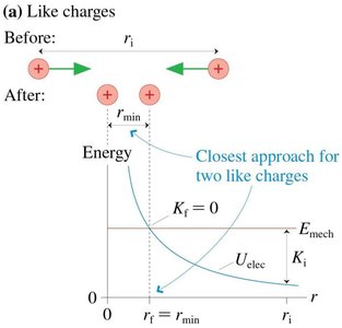
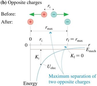
Potential Energy of Point Charges
The electric potential energy between two point charges q1 and q2 separated by distance r is:
Formula:
Key Point 1: For systems of multiple charges, sum the potential energy for each pair.
Key Point 2: Like charges repel, and opposite charges attract, affecting whether a particle is bound or unbound.
Example: A negative charge near a proton can be bound if its kinetic energy is less than the potential energy barrier.
Electric Potential and Equipotential Surfaces
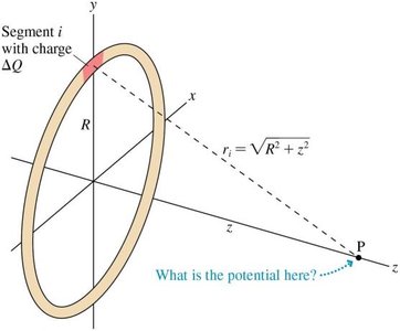
Electric Potential of Point Charges and Spheres
The electric potential at distance r from a point charge q is:
Formula:
Key Point 1: For a sphere with charge Q uniformly distributed, the potential outside the sphere is the same as for a point charge.
Key Point 2: The potential at the surface depends on the radius and total charge.
Electric Potential of Multiple Charges
The electric potential at a point due to several charges is the sum of the potentials from each charge:
Formula:
Key Point 1: Potentials are scalar quantities and add algebraically.
Example: The potential at a point equidistant from two equal and opposite charges is zero.
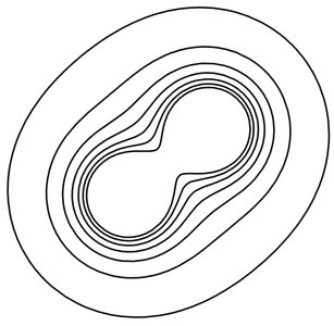
Equipotential Surfaces
Equipotential surfaces are imaginary surfaces where the electric potential is constant. The electric field is always perpendicular to these surfaces and points in the direction of decreasing potential.
Key Point 1: The spacing of equipotential lines indicates the strength of the electric field; closer lines mean stronger fields.
Key Point 2: Equipotential surfaces can be visualized as contour maps.

Electric Field and Potential Relationship
Connecting Potential and Field
The electric field and electric potential are related by:
Formula:
Key Point 1: The electric field is the negative gradient of the potential.
Formula:
Formula:
Electric Field from Equipotential Lines
The magnitude of the electric field between equipotential lines is given by:
Formula:
Key Point 1: The field is strongest where the equipotential lines are closest together.
Example: In a diagram with points A, B, and C, the electric field is greatest at the point with the closest spacing between lines.
Capacitance and Capacitors
Capacitance and Parallel-Plate Capacitors
Capacitance is the ability of a system to store charge per unit potential difference. For a parallel-plate capacitor:
Formula:
Formula:
Key Point 1: Capacitance depends only on geometry and the dielectric material between plates.
Key Point 2: The SI unit for capacitance is the farad (F).
Capacitors in Series and Parallel
Capacitors can be combined in series or parallel to achieve desired capacitance values:
Parallel:
Series:
Energy Stored in a Capacitor
The energy stored in a capacitor is:
Formula:
Key Point 1: Energy density in the electric field is
Example: Pulling apart the plates of a disconnected capacitor increases the stored energy, as work is done against the electric field.
Dielectrics
Dielectric Materials in Capacitors
When an insulator (dielectric) is placed between capacitor plates, it increases the capacitance by reducing the electric field.
Formula:
Key Point 1: The dielectric constant quantifies the effect of the material.
Key Point 2: The induced surface charge density is
Example: Inserting a dielectric into a disconnected capacitor decreases the potential difference between plates.
Current and Resistance
Current, Current Density, and Ohm's Law
Electric current is the flow of charge per unit time. In metals, electrons are the charge carriers.
Formula:
Formula: (current density)
Formula: (conductivity relation)
Formula: (resistance)
Formula: (Ohm's Law)
Key Point 1: The direction of current is defined as the direction positive charge would move.
Key Point 2: At a junction, the sum of currents entering equals the sum leaving (Kirchhoff's junction rule).
Magnetic Field
Magnetism and Magnetic Field Lines
Magnets have two poles: north and south. The magnetic field is represented by field lines, which indicate direction and strength.
Key Point 1: The direction of the magnetic field is shown by the alignment of a compass needle.
Key Point 2: A current-carrying wire produces a magnetic field; the right-hand rule determines its direction.
Biot-Savart Law for Moving Charges
The magnetic field due to a moving charge is given by:
Formula:
Formula:
Key Point 1: The direction of the magnetic field is determined by the cross product of velocity and position vector.
Tables
Comparison of Capacitance Changes
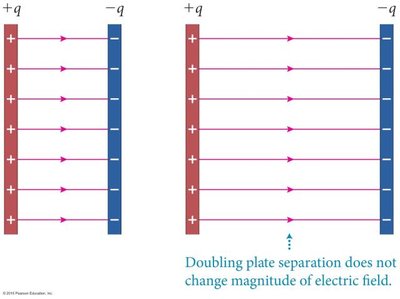
The following table summarizes how capacitance, electric field, and potential difference change when plate separation or area is altered in a disconnected parallel-plate capacitor:
Change | Capacitance (C) | Electric Field (E) | Potential Difference (ΔV) |
|---|---|---|---|
Double plate separation (d) | Halves | Constant | Doubles |
Halve plate area (A) | Halves | Doubles | Doubles |
Additional info: These results follow from , , and .
Capacitors in Series and Parallel
Configuration | Equivalent Capacitance |
|---|---|
Series | |
Parallel |
