Back
Backlecture 14
Study Guide - Smart Notes
 Tailored notes based on your materials, expanded with key definitions, examples, and context.
Faraday’s Law of Electromagnetic Induction
Definition and Formula
Faraday’s Law describes how a changing magnetic flux through a coil induces an electromotive force (emf). The average emf induced in a coil of N loops is given by:
Formula:
SI Unit of Induced Emf: volt (V)
The negative sign indicates that the induced emf opposes the change in magnetic flux (Lenz’s Law).
Magnetic flux, , is defined as , where B is the magnetic field, A is the area, and is the angle between the field and the normal to the area.
Physical Interpretation
An emf is generated if the magnetic flux changes due to variations in B, A, or .
The motional emf is a special case of Faraday’s Law.
Example: Emf Induced by a Changing Magnetic Field
A coil with 20 turns (N = 20), area 0.0015 m2, and a perpendicular magnetic field increases from 0.050 T to 0.060 T in 0.10 s.
Average induced emf:
Lenz’s Law
Lenz’s Law states that the induced emf and resulting current will always oppose the change in magnetic flux that produced them.
Reasoning Strategy:
Determine if the magnetic flux is increasing or decreasing.
Find the direction of the induced magnetic field needed to oppose the change.
Use the right-hand rule (RHR) to determine the direction of the induced current.
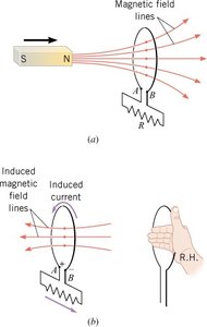
Conceptual Example: Moving Magnet and Loop
A permanent magnet approaches a loop of wire connected to a resistor.
The increasing magnetic field through the loop induces a current that creates a magnetic field opposing the increase (to the left).
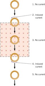
Conceptual Example: Moving Copper Ring in a Magnetic Field
A copper ring is dropped through a region with a constant horizontal magnetic field (into the page).
Induced current exists only when the ring enters or exits the field region (positions 2 and 4), not when fully inside or outside (positions 1, 3, 5).
The acceleration of the ring is reduced while it is entering or leaving the field due to the opposing induced current.
Electromagnetic Waves
Nature and Production of Electromagnetic Waves
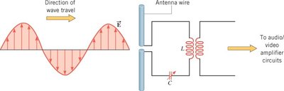
Electromagnetic (E&M) waves are oscillating electric and magnetic fields that propagate through space. They are produced by accelerating charges, such as those in an antenna connected to an oscillating voltage source.
Examples: Radio waves, light, X-rays, gamma rays
The electric field (E) and magnetic field (B) are perpendicular to each other and to the direction of wave propagation.
E&M waves are transverse and can travel through a vacuum.
Detection of Electromagnetic Waves
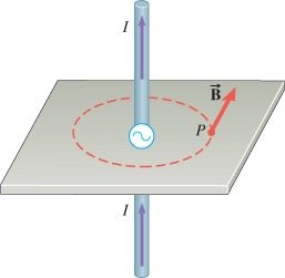
A receiving antenna wire parallel to the electric field detects the electric component, generating an oscillating current.
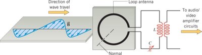
A loop antenna detects the magnetic component via Faraday’s Law, as the changing magnetic flux induces an oscillating current.
The Electromagnetic Spectrum
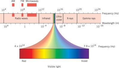
The electromagnetic spectrum encompasses all types of E&M waves, classified by wavelength and frequency. Visible light is a small portion of the spectrum.
Relationship: , where is the speed of light, is wavelength, and is frequency.
Visible light: ranges from about 380 nm (violet) to 750 nm (red).
Radio waves, microwaves, infrared, ultraviolet, X-rays, and gamma rays are other regions of the spectrum.
The Speed of Light
The speed of light in a vacuum is m/s.
Michelson’s device (1926) measured the speed of light using a rotating mirror and known distances.
Maxwell predicted the speed of light using the permittivity () and permeability () of free space:
Looking Back in Time
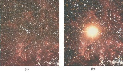
Light from distant astronomical events, such as supernovas, takes years to reach Earth, so observing them is like looking back in time.
1 light-year = km
The Reflection of Light: Mirrors
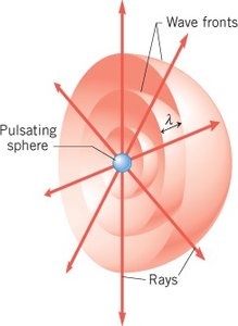
Wave Fronts and Rays
Wave fronts are surfaces of constant phase (e.g., crests), and rays are perpendicular to wave fronts, indicating the direction of energy propagation.
Spherical wave fronts become plane waves at large distances from the source.
Law of Reflection
The incident ray, reflected ray, and normal all lie in the same plane.
Angle of incidence () equals angle of reflection ():
Types of Reflection
Specular reflection: Reflected rays are parallel (e.g., mirrors, calm water).
Diffuse reflection: Reflected rays scatter in random directions (e.g., paper, rough surfaces).
Formation of Images by a Plane Mirror
The image formed by a plane mirror is:
Upright
The same size as the object
As far behind the mirror as the object is in front
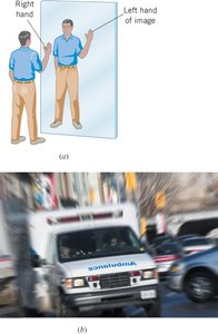
Reversed left-to-right
Emergency vehicles use reversed lettering so it appears normal in rear-view mirrors.
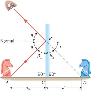
Virtual Images
Rays reflected from a mirror appear to come from a point behind the mirror, forming a virtual image.
None of the rays actually pass through the image location.
Image and Object Distances
For a plane mirror, the image distance () equals the object distance ():
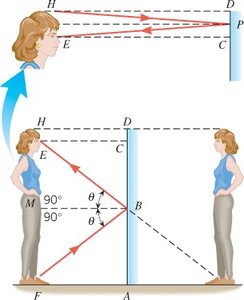
Minimum Mirror Height for Full Image
To see a full-length image, a person only needs a mirror half their height.
This is due to the geometry of reflection and similar triangles.
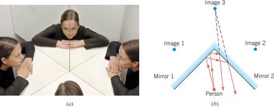
Multiple Reflections
When two mirrors intersect at a right angle, a person sees three images: one from each mirror and one from double reflection.