 Back
BackFundamentals of Electric Circuits: Series, Parallel, Power, Kirchhoff’s Rules, and RC Circuits
Study Guide - Smart Notes
 Tailored notes based on your materials, expanded with key definitions, examples, and context.
Fundamentals of Circuits
Circuit Symbols and Diagrams
Understanding electric circuits begins with recognizing the standard symbols used to represent various components. Circuit diagrams (schematics) use these symbols to show how components are connected, making analysis and construction easier.
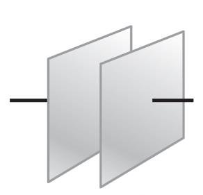
Capacitor: Two parallel lines represent a capacitor, which stores electric charge and energy.
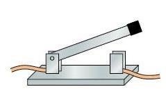
Switch: A device that can open or close a circuit, controlling current flow.

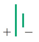
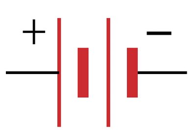
Battery: Represented by alternating long (positive) and short (negative) lines.
Lightbulb: Indicates a resistive load that emits light.

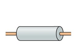
Resistor: A zigzag line, representing a component that resists current.

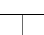
Wire: Straight lines connect components, representing conducting paths.
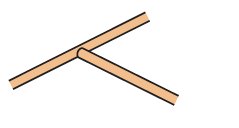
Junction: Where three or more wires meet, allowing current to split or combine.
Other symbols: Include ammeter, voltmeter, variable resistor, ground, and fuse.

Circuit diagrams use these symbols to represent real circuits, making it easier to analyze and communicate circuit design. 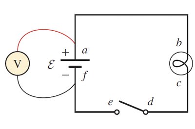
Resistors in Series and Parallel
Series and Parallel Connections
Resistors can be connected in two fundamental ways: series and parallel. The way they are connected affects the total (equivalent) resistance, current, and voltage distribution in the circuit.
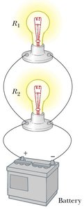
Series: Components are connected end-to-end, so the same current flows through each. The total resistance is the sum of individual resistances.
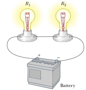
Parallel: Components are connected across the same two points, providing multiple paths for current. The voltage across each is the same, but the total current is the sum of the branch currents.
Identifying Series and Parallel: If you can move from point A to B without passing a junction, the components are in series. If there is a choice of paths, they are in parallel.
Resistors in Series
Current: Same through all resistors.
Voltage: Total voltage is the sum of voltage drops:
Equivalent Resistance:
Ohm's Law:
Note: The equivalent resistance in series is always greater than any individual resistor.
Resistors in Parallel
Voltage: Same across all resistors.
Current: Total current is the sum of branch currents:
Equivalent Resistance:
Ohm's Law:
Note: The equivalent resistance in parallel is always less than any individual resistor.
Summary Table: Series vs. Parallel
Property | Series | Parallel |
|---|---|---|
Current | Same through all | Adds: |
Voltage | Adds: | Same across all |
Equivalent Resistance |
Example: Resistor Ladder
To find the equivalent resistance of a complex network, reduce the circuit step by step, replacing series and parallel groups with their equivalents until only one resistor remains.
Electric Power in Circuits
Power Dissipation
Electric power is the rate at which energy is transferred or converted. In resistors, power is dissipated as heat.
General formula:
Using Ohm's Law:
Choose the formula that matches the known quantities in the problem.
Example: Household Heater
Given: ,
Power:
Energy for 30 days, 3 hours/day:
Cost at cents/kWh:
Example: Light Bulbs in Series and Parallel
Two 100 Ω bulbs connected to a 24 V battery:
Series: , , per bulb
Parallel: , , per bulb
Bulbs in parallel are brighter because each receives the full voltage.
Potential Changes and Kirchhoff’s Rules
Kirchhoff’s Loop Rule
The sum of potential differences around any closed loop is zero, reflecting energy conservation:
Apply sign conventions: voltage rises (battery from - to +) are positive, drops (resistor in current direction) are negative.
Kirchhoff’s Junction Rule
The sum of currents entering a junction equals the sum leaving (charge conservation):
Solving Multi-Loop Circuits
Assign current directions and label them.
Apply the junction rule at each node.
Apply the loop rule for independent loops.
Solve the resulting system of equations for unknown currents.
Electromotive Force (emf), Terminal Voltage, and Internal Resistance
Real vs. Ideal Batteries
Ideal battery: Maintains constant voltage regardless of current.
Real battery: Has internal resistance , so terminal voltage drops as current increases.
emf (): The open-circuit voltage of a battery (no current drawn).
Terminal voltage:
Example: Internal Resistance Calculation
Given: , ,
Current:
Internal resistance:
Measuring Instruments: Ammeter, Voltmeter, Ohmmeter
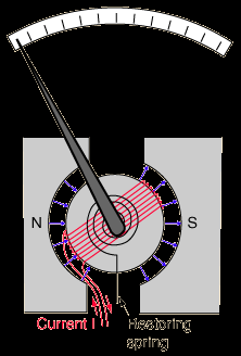
Ammeter
Measures current; connected in series.
Should have very low resistance to minimize circuit disturbance.
Often based on a galvanometer with a shunt resistor.
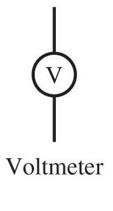
Voltmeter
Measures voltage; connected in parallel.
Should have very high resistance to minimize current draw.
Ohmmeter
Measures resistance; connected across an isolated resistor (circuit off).
Contains a battery and measures current to infer resistance.
RC Circuits: Charging and Discharging Capacitors
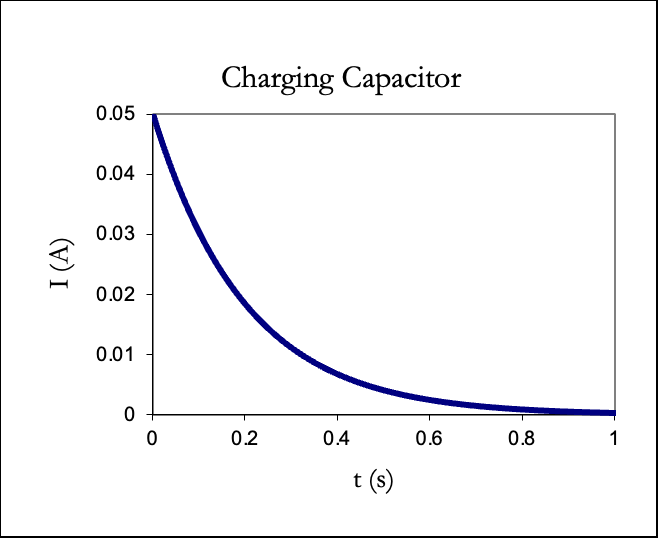
Charging a Capacitor
When a capacitor is connected to a battery through a resistor, it charges over time, not instantaneously. The process is governed by the time constant .
Charge as a function of time: , where
Current as a function of time: , where
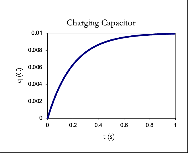
After one time constant (), the capacitor reaches about 63% of its final charge.
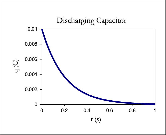
Discharging a Capacitor
When a charged capacitor is allowed to discharge through a resistor, the charge and current decrease exponentially:
Charge:
Current: , where
Summary Table: RC Circuit Equations
Process | Charge | Current | Capacitor Voltage |
|---|---|---|---|
Charging | |||
Discharging |
Time constant: determines how quickly the capacitor charges or discharges.
Example: RC Circuit Calculation
Given: , ,
At ,
Charge:
Voltage across capacitor:
Key Takeaways
Master circuit symbols and schematic diagrams for effective communication and analysis.
Understand the rules for combining resistors in series and parallel, and how to calculate equivalent resistance.
Apply Ohm’s Law and power formulas to analyze circuit performance.
Use Kirchhoff’s rules for complex circuits with multiple loops and junctions.
Recognize the impact of real measuring instruments and internal resistance in practical circuits.
Analyze the time-dependent behavior of RC circuits using exponential equations and the time constant.
