 Back
BackGeometric Optics: Reflection, Refraction, Lenses, and the Human Eye
Study Guide - Smart Notes
 Tailored notes based on your materials, expanded with key definitions, examples, and context.
Reflection and the Ray Model of Light
The Ray Model of Light
Geometric optics is based on the assumption that light travels in straight lines, called rays. This model allows us to analyze the behavior of light using geometry, which is especially useful for understanding phenomena such as reflection and refraction.
Light rays originate from a source and travel indefinitely unless interrupted.
We see objects when light rays from them reach our eyes.
Light can be reflected off surfaces, enabling us to see non-luminous objects.
Geometric optics treats light as a particle for practical analysis.

Additional info: The ray model is foundational for analyzing optical systems such as mirrors and lenses.
Law of Reflection
The law of reflection governs how light bounces off surfaces. It states that the angle of incidence (incoming angle) is equal to the angle of reflection, both measured relative to the normal (perpendicular) to the surface.
Angle of incidence (): Angle between incoming ray and the normal.
Angle of reflection (): Angle between reflected ray and the normal.
Law of Reflection:
Example: When light strikes a mirror, the reflected ray leaves at the same angle as it arrived.
Types of Reflection
Reflection can occur in two main forms, depending on the surface:
Specular reflection: Occurs on smooth surfaces (e.g., mirrors), where reflected rays remain parallel.
Diffuse reflection: Occurs on rough surfaces, scattering light in many directions.
The law of reflection applies to both types.
Example: Mirrors produce clear images due to specular reflection, while paper produces no image due to diffuse reflection.


Additional info: Specular reflection is essential for optical devices, while diffuse reflection is responsible for the visibility of most objects.
Images in Reflection
Specular reflection allows the formation of images, such as seeing oneself in a mirror. Diffuse reflection does not form images because light is scattered.


Plane Mirrors
A plane mirror is a flat, smooth reflecting surface. Images seen in plane mirrors appear to originate from a point behind the mirror, called the virtual image.
Virtual image: Light does not pass through the image; it appears to be behind the mirror.
Real image: Light actually passes through the image location.


Measuring Distances
To analyze image formation, we define object and image positions relative to the mirror.


Spherical Mirrors
Spherical mirrors are curved mirrors, either concave (inner surface) or convex (outer surface). They focus or diverge light rays depending on their shape.
Concave mirror: Inner surface; focuses parallel rays to a point (focus).
Convex mirror: Outer surface; diverges rays.
Focal Point and Focal Length
The focal point is where parallel rays converge after reflection from a concave mirror. The focal length () is the distance from the mirror to the focal point, and for a spherical mirror, $f$ is half the radius of curvature ():
Ray Diagrams for Mirrors
Ray diagrams are used to determine image location and properties. Three principal rays are drawn from the object:
Ray parallel to principal axis, reflected through the focal point.
Ray through the focal point, reflected parallel to principal axis.
Ray through the center of curvature, reflected back on itself.
The intersection of these rays determines the image location.
The Mirror Equation
The mirror equation relates object distance (), image distance (), and focal length ():
Additional info: This equation is derived from similar triangles formed by the object, image, and focal point.
Magnification
Magnification () describes how much larger or smaller the image is compared to the object:
Negative indicates an inverted image.
Sign Conventions for Mirrors
Positive direction is defined as the direction light travels. Concave mirrors have positive focal lengths, convex mirrors have negative focal lengths.
Mirror Properties
Concave mirrors: Positive focal length; can produce real or virtual images.
Convex mirrors: Negative focal length; produce only virtual images.
Example: Car mirrors are convex, making objects appear smaller and farther away.
Refraction and Lenses
Refraction
Refraction occurs when light passes from one medium to another, changing speed and direction. The degree of bending depends on the index of refraction ():
, where is the speed of light in vacuum and is the speed in the medium.
Example: Light bends when entering water from air due to different indices of refraction.
Snell's Law
Snell's Law relates the angles of incidence and refraction to the indices of refraction:


Example: Optical illusions occur when our brains assume light travels in straight lines, but refraction alters its path.
Total Internal Reflection
Total internal reflection occurs when light moves from a medium with higher index of refraction to one with lower index, and the angle of incidence exceeds the critical angle. The light is completely reflected within the medium.
Critical angle: The minimum angle for total internal reflection.
Example: Fiber optics use total internal reflection to transmit light efficiently.
Lenses
Lenses use refraction to focus or diverge light. There are two main types:
Converging (convex) lens: Focuses parallel rays to a point.
Diverging (concave) lens: Scatters rays outward.

Additional info: Lenses are often approximated as thin for calculations.
Ray Diagrams for Lenses
Ray diagrams for lenses follow similar rules as mirrors, but rays pass through the lens:
Ray parallel to principal axis, refracted through the focal point.
Ray through the focal point, refracted parallel to principal axis.
Ray straight through the center of the lens.


The Thin Lens Equation
The thin lens equation is used to find image location:

Converging lenses: Positive focal length. Diverging lenses: Negative focal length.
Sign Conventions for Lenses
For lenses, positive image distance is on the opposite side from the object, since light passes through the lens.

Combination of Lenses
Optical instruments often use multiple lenses for magnification. The image formed by the first lens becomes the object for the second lens.


The Human Eye
Structure of the Human Eye
The human eye functions as a lens system, focusing light onto the retina. The retina contains rods (detect low light) and cones (detect color). The cornea and lens focus light, while the iris controls the amount entering the eye.
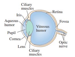
Fovea: Area of sharpest vision due to high concentration of rods and cones.
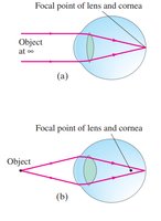
Focusing and Corrective Lenses
The eye adjusts its lens to focus on objects at varying distances. The near point is the closest point the eye can focus, and the far point is the farthest.
Corrective lenses are used to address vision problems:
Myopia (nearsightedness): Eye focuses nearby objects but not distant ones; corrected with diverging lenses.
Hyperopia (farsightedness): Eye focuses distant objects but not nearby ones; corrected with converging lenses.
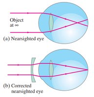
Ray Diagrams for Vision Correction
Corrective lenses create virtual images at the near or far points, allowing comfortable vision.
The Lensmaker's Equation
For thick lenses, the Lensmaker's Equation relates the focal length to the radii of curvature of each lens surface:
Additional info: is positive for convex surfaces, is negative for concave surfaces.
Summary Table: Index of Refraction
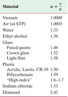
The index of refraction varies by material, affecting how much light bends:
Material | Index of Refraction (n) |
|---|---|
Vacuum | 1.0000 |
Air (at STP) | 1.0003 |
Water | 1.33 |
Ethyl alcohol | 1.36 |
Glass (Fused quartz) | 1.46 |
Glass (Crown glass) | 1.52 |
Glass (Light flint) | 1.58 |
Plastic (Acrylic, Lucite, CR-39) | 1.50 |
Plastic (Polycarbonate) | 1.59 |
Plastic (High-index) | 1.6–1.7 |
Sodium chloride | 1.53 |
Diamond | 2.42 |
Additional info: Higher index means greater bending of light.
