 Back
BackInductance and LC/RL Circuits: Concepts and Applications
Study Guide - Smart Notes
 Tailored notes based on your materials, expanded with key definitions, examples, and context.
Inductance and Circuits
Introduction to Inductance
Inductance is a fundamental property of electrical circuits, particularly those containing coils or solenoids. It describes the ability of a circuit element to induce an electromotive force (emf) as a result of a changing current. Inductance is measured in henries (H), where 1 H = 1 Wb/A (weber per ampere).
Inductor: A passive circuit element that stores energy in its magnetic field when current flows through it.
Symbol: L
Unit: Henry (H)
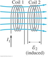
Mutual Inductance
Definition and Principle
Mutual inductance occurs when a change in current in one coil induces an emf in a nearby coil. This is the principle behind transformers and many wireless charging systems.
Mutual Inductance (M): The proportionality constant relating the emf induced in one coil to the rate of change of current in another coil.
Formula:
Unit: Henry (H)
Application: Used in transformers to transfer energy between circuits.
Self-Inductance
Definition and Formula
Self-inductance is the property of a single coil (or circuit) to induce an emf in itself as the current changes. This is a key concept in understanding how inductors resist changes in current.
Self-Inductance (L): The proportionality constant relating the emf induced in a coil to the rate of change of current in itself.
Formula:
Unit: Henry (H)
Energy Stored in an Inductor
Magnetic Energy Storage
When current flows through an inductor, energy is stored in its magnetic field. The amount of energy stored depends on the inductance and the current.
Formula:
Interpretation: The energy is proportional to the square of the current and the inductance.
Example: If L = 2 H and I = 3 A, then J.
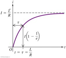
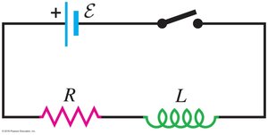
RL Circuits
RL Circuit Behavior and Time Constant
An RL circuit consists of a resistor (R) and an inductor (L) in series with a voltage source. When the switch is closed, the current does not immediately reach its maximum value due to the inductor's opposition to changes in current. The time constant (τ) characterizes how quickly the current approaches its steady-state value.
Time Constant:
Current Growth:
Steady-State Current:
At t = 0: (current starts at zero)
At t → ∞: (current reaches maximum value)
Example Problem
Given:
(a) Initial rate of current change:
(b) Long-term current:
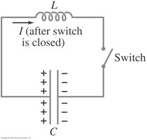
LC Circuits
Oscillations in LC Circuits
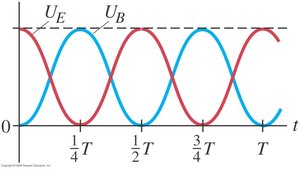
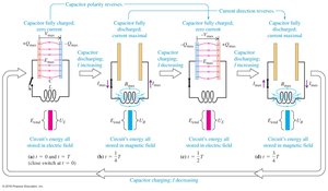
An LC circuit consists of an inductor (L) and a capacitor (C) connected together. When the capacitor is charged and the switch is closed, energy oscillates between the electric field of the capacitor and the magnetic field of the inductor. This forms the basis for many oscillatory circuits, such as radio tuners.
Oscillation Frequency:
Energy Exchange: Energy alternates between the capacitor (electric field) and the inductor (magnetic field).
Applications: Used in radio receivers and transmitters for tuning to specific frequencies.
Energy in LC Circuits
Maximum Energy in Capacitor:
Maximum Energy in Inductor:
At any instant, the total energy is conserved and oscillates between and .
Summary Table: RL vs. LC Circuits
Property | RL Circuit | LC Circuit |
|---|---|---|
Components | Resistor, Inductor | Inductor, Capacitor |
Behavior | Current grows/exponentially decays | Oscillatory (sinusoidal) current and voltage |
Energy Storage | Magnetic field in inductor | Alternates between electric field (capacitor) and magnetic field (inductor) |
Time Constant / Frequency |
