 Back
BackInductance and RL/LC Circuits: Concepts, Equations, and Applications
Study Guide - Smart Notes
 Tailored notes based on your materials, expanded with key definitions, examples, and context.
Inductance
Introduction to Inductance
Inductance is a fundamental property of electrical circuits that describes the opposition to changes in current due to the magnetic field generated by the current itself. It plays a crucial role in the behavior of circuits containing coils or solenoids, and is measured in Henrys (H).
Inductance (L): The property of a circuit or component that causes an electromotive force (emf) to be induced by a change in current.
SI Unit: Henry (H), where 1 H = 1 V·s/A = 1 Ω·s.
Physical Origin: Inductance arises from the magnetic flux linkage with the circuit.
Mutual Inductance
Definition and Principles
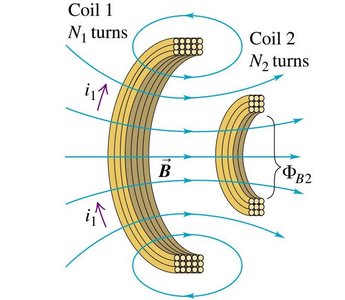
Mutual inductance occurs when a changing current in one coil induces an emf in a neighboring coil due to the changing magnetic flux through the second coil. This is the principle behind transformers and many types of sensors.
Mutual Inductance (M): Quantifies the induced emf in one coil due to the rate of change of current in another coil.
Formulas:
Magnetic Flux Linkage:
Applications: Transformers, wireless charging, and inductive sensors.
Self-Inductance and Inductors
Self-Induction and Lenz's Law
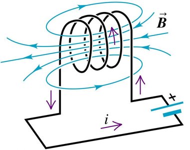
Self-inductance is the phenomenon where a changing current in a circuit induces an emf in the same circuit, opposing the change according to Lenz's Law. Inductors are components designed to maximize this effect.
Self-Induced emf:
Inductance (L): , where is the number of turns and is the magnetic flux.
Physical Meaning: Inductance depends on the geometry of the coil and the magnetic permeability of the core material.
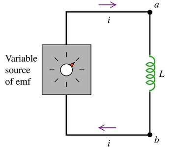
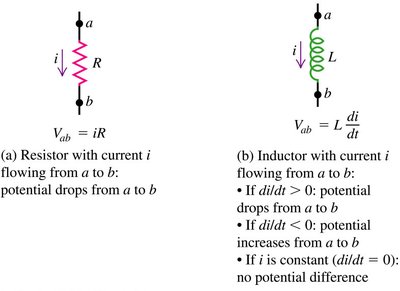
Potential Across an Inductor
Comparison with Resistors
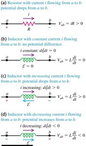
The potential difference across an inductor depends on the rate of change of current, in contrast to a resistor where it depends on the current itself. The self-induced emf always opposes changes in current.
Resistor:
Inductor:
Key Points:
If , potential drops from a to b.
If , potential increases from a to b.
If is constant, .
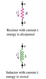
Energy in Inductors and Magnetic Fields
Energy Storage
Unlike resistors, which dissipate energy as heat, inductors store energy in their magnetic fields. The energy stored in an inductor is proportional to the square of the current.
Energy Stored:
Energy Density: , where is the magnetic field and is the permeability of free space.
Comparison: Capacitors store energy in electric fields, inductors in magnetic fields.
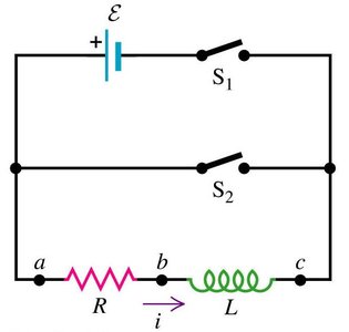
RL Circuits
Time Constant and Current Growth/Decay
RL circuits consist of resistors and inductors. When the circuit is switched on or off, the current does not change instantaneously but follows an exponential behavior characterized by the time constant .
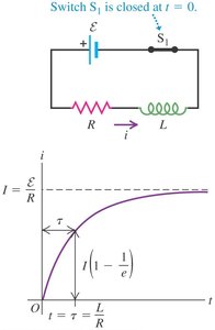
Current Growth (Switch On):
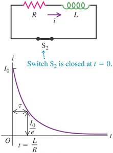
Current Decay (Switch Off):
Time Constant:
LC Circuits
Oscillations and Energy Exchange
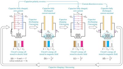
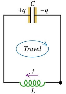
An LC circuit contains an inductor and a capacitor. The energy oscillates between the electric field of the capacitor and the magnetic field of the inductor, resulting in electrical oscillations analogous to mechanical simple harmonic motion.
Differential Equation:
Solution: , where
Current:
Total Energy: (remains constant in ideal LC circuit)
LRC Circuits
Damped Oscillations
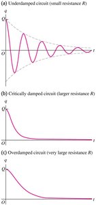
An LRC circuit contains an inductor, resistor, and capacitor in series. The presence of resistance causes the oscillations to decay over time, a phenomenon known as damping. The behavior depends on the relative values of L, R, and C.
Underdamped: Oscillatory decay (small R)
Critically damped: Fastest return to equilibrium without oscillation (intermediate R)
Overdamped: Slow return to equilibrium without oscillation (large R)
Summary Table: Energy Storage in Circuit Elements
Element | Energy Storage Formula | Physical Field |
|---|---|---|
Capacitor | Electric Field | |
Inductor | Magnetic Field |
