 Back
BackInductors and Electromagnetic Oscillations in Circuits
Study Guide - Smart Notes
 Tailored notes based on your materials, expanded with key definitions, examples, and context.
Inductors in Circuits
Introduction to Inductors
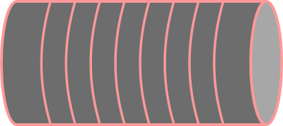
Inductors are fundamental components in electrical circuits, especially where magnetic flux and time-varying currents are involved. An inductor is typically a coil of wire (often resembling a mini solenoid) that stores energy in its magnetic field when current flows through it. Inductors can interact with each other via their magnetic fields, leading to important phenomena such as mutual and self-inductance.
Mutual Inductance
Definition and Physical Basis
Mutual inductance occurs when two coils are placed near each other, and a changing current in one coil induces an electromotive force (emf) in the other. This is a direct consequence of Faraday's Law of Induction. The induced emf in the second coil is proportional to the rate of change of current in the first coil:
Key Point 1: Changing current in Coil 1 produces a changing magnetic field, which passes through Coil 2, altering its magnetic flux.
Key Point 2: The induced emf in Coil 2 opposes the change in flux (Lenz's Law).
The mutual inductance M is defined by:
where is the emf induced in Coil 2, and is the rate of change of current in Coil 1.
Example: Two solenoids placed coaxially so that the magnetic field of one links the other.
Self-Inductance
Definition and Physical Basis
Self-inductance is the property of a single coil to induce an emf in itself when the current through it changes. A constant current produces no emf, but a changing current alters the magnetic flux, inducing an emf that opposes the change (Lenz's Law):
Key Point 1: The induced emf is proportional to the rate of change of current in the coil.
Key Point 2: The self-inductance L is a geometric property, depending on the coil's dimensions and number of turns.
The self-induced emf is given by:
where is the inductance of the coil.
Calculating Inductance
Solenoid Inductance
The inductance of a solenoid depends on its geometry:
Number of turns ()
Cross-sectional area ()
Length ()
The inductance is given by:
where is the permeability of free space.
Inductance of Coaxial Cylinders
For two coaxial cylinders, the magnetic field is confined to the region between the cylinders, and the inductance can be calculated using the geometry of the system.
Energy Storage in Inductors
Magnetic Energy
Inductors store energy in their magnetic fields. The energy stored is given by:
where is the current through the inductor. This is analogous to the energy stored in a capacitor, , but for magnetic fields instead of electric fields.
LR Circuits
Time-Dependent Behavior
An LR circuit consists of an inductor and a resistor in series. When a voltage is applied, the current does not immediately reach its maximum value due to the inductor's opposition to changes in current. The current as a function of time is:
where is the time constant of the circuit.
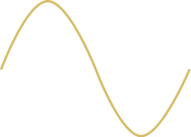
LC Circuits: Electromagnetic Oscillations
Oscillatory Behavior
An LC circuit contains only an inductor and a capacitor. When the capacitor is initially charged and the circuit is closed, energy oscillates between the electric field of the capacitor and the magnetic field of the inductor. The charge on the capacitor varies sinusoidally:
where is the angular frequency of oscillation.
LRC Circuits: Damped Oscillations
Energy Dissipation
An LRC circuit includes a resistor, inductor, and capacitor. The resistor causes energy to dissipate, resulting in damped oscillations. The angular frequency of the damped oscillator is:
Reactance and Impedance
Inductive and Capacitive Reactance
Both inductors and capacitors oppose changes in current, a property called reactance. The inductive reactance is:
The capacitive reactance is:
Reactance depends on the frequency of the alternating current (AC) source.
Impedance
The total opposition to current in an AC circuit is called impedance (), which combines resistance and reactance:
Phasor Diagrams
Visualizing Voltages and Currents
Phasor diagrams are used to represent the phase relationships between voltages and currents in AC circuits. The voltages across resistors, inductors, and capacitors can lead or lag the current, and their vector sum gives the total voltage amplitude.
Summary Table: Key Formulas
Quantity | Formula | Description |
|---|---|---|
Self-Induced emf | Emf induced in a coil by changing its own current | |
Mutual Induced emf | Emf induced in a second coil by changing current in the first | |
Inductance (Solenoid) | Inductance of a solenoid | |
Energy Stored | Magnetic energy in an inductor | |
Inductive Reactance | Opposition to AC by an inductor | |
Capacitive Reactance | Opposition to AC by a capacitor | |
Impedance | Total opposition to AC | |
LC Oscillation Frequency | Natural frequency of LC circuit |
