 Back
BackInterference and Diffraction: The Wave Nature of Light
Study Guide - Smart Notes
 Tailored notes based on your materials, expanded with key definitions, examples, and context.
Chapter 26: Interference and Diffraction
Introduction to Interference and Diffraction
While geometric optics treats light as rays, the phenomena of interference and diffraction reveal the wave nature of light. These effects are crucial for understanding many natural and technological applications, such as anti-reflective coatings and the analysis of atomic structures.
Thin film coatings reduce unwanted reflections on camera lenses by exploiting interference.
Diffraction gratings are used in spectroscopy to analyze light from chemical reactions or stars.
X-ray diffraction helps determine the structure of crystalline materials.
This chapter covers:
Interference and coherent sources
Two-source interference of light
Interference in thin films
Diffraction from single and multiple slits
X-ray diffraction and atomic crystals
Resolving power and aperture size
Holography
Interference and Coherent Sources
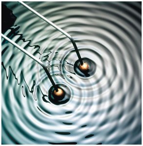
Interference occurs when two or more waves overlap in space, resulting in a new wave pattern. The principle of linear superposition states that the resultant displacement at any point is the sum of the displacements due to each wave individually.
Coherent sources are two light sources that emit waves of the same wavelength and phase.
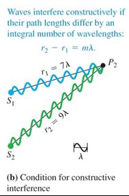
When two waves meet in phase (crest meets crest), constructive interference occurs, producing a bright region.
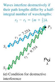
When a crest meets a trough, destructive interference occurs, resulting in a dark region.
The conditions for interference are:
Constructive interference: where
Destructive interference: where
Two-Source Interference of Light (Young's Double-Slit Experiment)
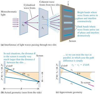
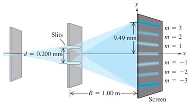
One of the most important demonstrations of light's wave nature is the double-slit experiment, first performed by Thomas Young in 1800. A monochromatic light source illuminates two closely spaced slits, creating an interference pattern of bright and dark fringes on a screen.
Let the slits be separated by distance and the screen be at distance from the slits.
The path difference for light reaching a point on the screen is .
Constructive interference (bright fringes):
Destructive interference (dark fringes):
is the angle from the central axis to the point .
Fringe Positions on the Screen
The positions of the bright and dark fringes on the screen can be calculated as:
Bright fringes:
Dark fringes:
is the distance from the central maximum to the th bright or dark fringe.
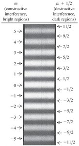
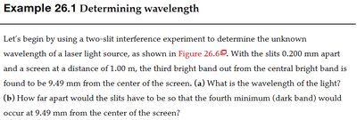
Example: Determining Wavelength
Suppose a double-slit experiment is performed with slits 0.200 mm apart and a screen 1.00 m away. The third bright band is found 9.49 mm from the center. To find the wavelength:
Given: mm, m, mm,
Use to solve for :
For the position of the fourth minimum (dark band) at the same location, use the dark fringe formula and solve for .
m (bright regions) | m + 1/2 (dark regions) |
|---|---|
5 | 11/2 |
4 | 9/2 |
3 | 7/2 |
2 | 5/2 |
1 | 3/2 |
0 | 1/2 |
-1 | -1/2 |
-2 | -3/2 |
-3 | -5/2 |
-4 | -7/2 |
-5 | -9/2 |
Table Purpose: This table classifies the positions of bright (constructive) and dark (destructive) interference fringes by their order number .
Additional info: The above content provides a foundation for understanding more advanced topics such as thin film interference, diffraction gratings, and the resolving power of optical instruments, which are covered in subsequent sections of the chapter.
