 Back
BackInterference of Light: Double-Slit and Thin-Film Phenomena
Study Guide - Smart Notes
 Tailored notes based on your materials, expanded with key definitions, examples, and context.
Interference of Light
Introduction to Interference
Interference is a phenomenon that occurs when two or more waves overlap and combine to form a new wave pattern. In the context of light, interference provides strong evidence for the wave nature of light. This chapter explores the types of light, the conditions for interference, and the applications of interference in double-slit and thin-film experiments.
Incoherent and Coherent Light
Definitions and Properties
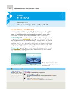
Incoherent Light: Light whose waves are not in phase with each other. Everyday sources like lightbulbs emit incoherent light, resulting in a random superposition of waves. The effect is analogous to the choppy surface of water during heavy rain.
Coherent Light: Light consisting of waves of the same wavelength and phase. Coherent light can be produced by lasers or by filtering light through a narrow slit to select a single wavefront.
Wavefront: A surface over which the light wave has a constant phase. Regular wavefronts are characteristic of coherent light.
Interference of Coherent Light
Young's Double-Slit Experiment
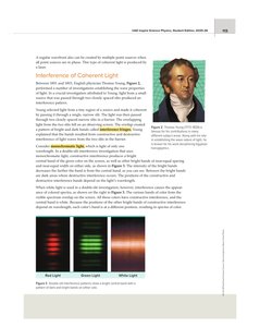
Thomas Young's double-slit experiment (1801–1803) was pivotal in demonstrating the wave nature of light. By passing light through two closely spaced slits, Young observed a pattern of bright and dark bands (interference fringes) on a screen, which could only be explained by the superposition of waves.
Constructive Interference: Occurs when waves from the two slits arrive in phase, producing bright bands.
Destructive Interference: Occurs when waves arrive out of phase, producing dark bands.
Monochromatic Light: Light of a single wavelength produces evenly spaced bright and dark bands.
White Light: Produces colored spectra due to the different wavelengths of visible light interfering at different positions.
Generation of Coherent Light for Interference
Single and Double Slit Setup
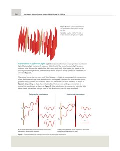
To produce coherent light from an incoherent source, light is first passed through a narrow slit, selecting a small region of the wavefront. This light then passes through two closely spaced slits, generating two coherent wavefronts that interfere on a screen.
Constructive interference produces bright bands where the path difference is an integer multiple of the wavelength.
Destructive interference produces dark bands where the path difference is a half-integer multiple of the wavelength.
Double-Slit Interference: Analysis and Equations
Mathematical Description
The double-slit experiment can be analyzed using geometry and trigonometry. The positions of bright and dark bands depend on the wavelength of light, the distance between the slits, and the distance to the screen.
Key Equation: The position x of the m-th order bright band is given by:
Where m is the order of the band (0 for central, 1 for first-order, etc.), λ is the wavelength, L is the distance from the slits to the screen, and d is the slit separation.
For small angles, , simplifying calculations.
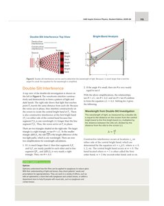
Example Problem: Calculating Wavelength
Given: m, m, m
Find:
Substitute values:
m = 668 nm
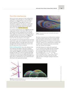
Thin-Film Interference
Principle and Applications
Thin-film interference occurs when light reflects from the upper and lower boundaries of a thin film, such as a soap bubble or oil slick. The resulting colors are due to constructive and destructive interference between the reflected waves.
When the film thickness is a quarter of the wavelength in the film, constructive interference enhances that color.
Inversion of the wave occurs upon reflection from a medium with a higher index of refraction.
The condition for constructive interference depends on the number of inversions and the path difference.
Mathematical Conditions for Thin-Film Interference
If one wave is inverted, constructive interference occurs when:
If both or neither wave is inverted, constructive interference occurs when:
Where d is the film thickness, λ is the wavelength in vacuum, n is the refractive index of the film, and m is an integer (0, 1, 2, ...).
Example Problem: Minimum Thickness for Color
Given: nm,
Find: Minimum thickness for constructive interference (yellow-green light)
nm
Interference in Nature and Technology
Natural Examples
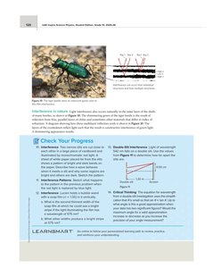
Many insects and beetles display iridescent colors due to thin-film interference in their exoskeletons, which consist of multiple layers with different refractive indices.
Technological Applications
Anti-reflective coatings on eyeglasses use thin-film interference to reduce glare by causing destructive interference for certain wavelengths of light.
Summary Table: Interference Conditions
Type of Interference | Inversion Condition | Path Difference | Film Thickness (d) |
|---|---|---|---|
Constructive (one inversion) | One wave inverted | ||
Constructive (both/none inverted) | Both or none inverted | ||
Destructive (one inversion) | One wave inverted | ||
Destructive (both/none inverted) | Both or none inverted |
Key Takeaways
Interference patterns provide strong evidence for the wave nature of light.
Double-slit and thin-film interference are foundational experiments in wave optics.
Understanding interference is essential for applications in optics, such as anti-reflective coatings and the analysis of natural phenomena.
