 Back
BackWeek 5 Lec. 2
Study Guide - Smart Notes
 Tailored notes based on your materials, expanded with key definitions, examples, and context.
Kirchhoff’s Rules and Circuit Analysis
Kirchhoff’s Loop Rule
The Kirchhoff’s Loop Rule states that the algebraic sum of the potential differences (including emfs and resistive elements) around any closed loop in a circuit must equal zero. This is a consequence of the conservation of energy in electrical circuits.
Loop Rule Equation:
Emf (Electromotive Force): Represents the energy supplied by a battery or source per unit charge.
Resistive Elements: Potential drops across resistors are given by Ohm’s Law: .
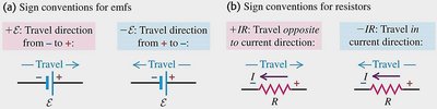
Sign Conventions in Loops
When traversing a loop, the sign of each voltage term depends on the direction of travel relative to the polarity of the emf or the direction of current through resistors.
For emfs:
Travel from negative to positive terminal:
Travel from positive to negative terminal:
For resistors:
Travel in the direction of current:
Travel opposite to current:
Worked Example: Multi-Loop Circuit
To analyze a circuit with multiple loops and sources:
Simplify the circuit using equivalent resistors.
Label currents and their directions.
Apply the Junction Rule at nodes (conservation of charge).
Choose independent loops and apply the Loop Rule.
Solve the resulting simultaneous linear equations for unknown currents.
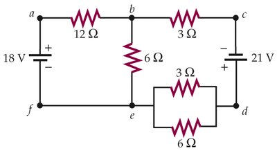
Example Equations:
For left loop:
For right loop:
Junction rule:
Solving these equations yields the values and directions of the currents.
Key Concepts for Circuit Analysis
Resistors in Series:
Resistors in Parallel:
Multiple Voltage Sources: Can be combined in series or parallel to adjust total emf and current capability.
Ammeters and Voltmeters: Ammeters are connected in series (ideal resistance = 0), voltmeters in parallel (ideal resistance = ∞).
RC Circuits: Circuits containing resistors and capacitors exhibit time-dependent behavior.
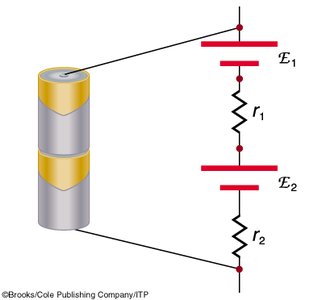
Multiple Voltage Sources
Combining Batteries in Series
When batteries are connected in series, their emfs add, but so do their internal resistances.
Total emf:
Total internal resistance:
Terminal voltage:
Measuring Current and Voltage
Ammeters and Voltmeters
To measure the current through a resistor and the voltage across it:
Ammeters: Connect in series with the resistor. Ideal ammeter has zero resistance.
Voltmeters: Connect in parallel with the resistor. Ideal voltmeter has infinite resistance.
Correct configuration: Ammeters in series, voltmeters in parallel.
RC Circuits: Charging a Capacitor
Time-Dependent Charging
When a capacitor is charged in a series circuit with a resistor and a battery, the charge and current change over time.
Initial condition: Capacitor uncharged, all voltage across resistor.
Final condition: Capacitor fully charged, all voltage across capacitor, current is zero.
Kirchhoff’s Loop Rule:
Current:
Time constant: (units: seconds)
Charge as a function of time:
, where is the maximum charge.
Current as a function of time:
To find the time to reach a certain fraction of maximum charge:
Set (e.g., for 90%)
Solve:
Example Calculation
For a 12.0 V battery, 50.0 Ω resistor, and 100.0 μF capacitor:
Time constant: s
To reach 90% charge: s
Summary Table: Circuit Elements and Measurement
Element | Connection | Ideal Resistance | Measurement |
|---|---|---|---|
Resistor | Series/Parallel | n/a | Voltage drop, current |
Ammeters | Series | 0 Ω | Current |
Voltmeters | Parallel | ∞ Ω | Voltage |
Additional info:
Magnetism and Lorentz force are listed as key concepts but not covered in detail in these notes.
Images included are directly relevant to sign conventions, circuit analysis, and battery combinations.
