 Back
BackWeek 7 Lec. 1
Study Guide - Smart Notes
 Tailored notes based on your materials, expanded with key definitions, examples, and context.
Torque on a Current Loop
Calculation of Torque
The torque experienced by a current-carrying loop in a magnetic field is a fundamental concept in electromagnetism. The torque depends on the geometry of the loop, the current, and the orientation of the loop relative to the magnetic field.
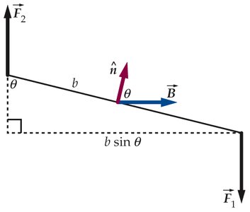
Torque Formula: The torque \( \tau \) about the center of a rectangular loop is given by: where I is the current, A is the area of the loop, B is the magnetic field, and \( \phi \) is the angle between the normal to the loop and the magnetic field.
Magnetic Dipole Moment: Defined as \( \vec{\mu} = IAn \), where n is the unit vector normal to the loop.
Maximum Torque: Occurs when the loop is parallel to the magnetic field (\( \phi = 90^\circ \)).
Direction: The torque tends to align the normal vector of the loop with the magnetic field.
Example: For a flat loop (not necessarily rectangular), the torque is still given by \( \tau = IAB \sin \phi \).

Magnetic Field of a Moving Charge
Field Generation by Moving Charges
A moving electric charge generates a magnetic field. The direction and shape of the field depend on the velocity of the charge and its position relative to the observer.
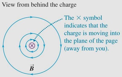
Field Lines: The magnetic field lines form concentric circles around the path of the moving charge, lying in planes perpendicular to the velocity vector.
Right-Hand Rule: The direction of the field lines can be determined using the right-hand rule: if the thumb points in the direction of the velocity, the fingers curl in the direction of the magnetic field lines.
Example: A charge moving into the plane of the page produces circular field lines around its path.
Magnetic Field of a Current Element
Field Generation by Currents
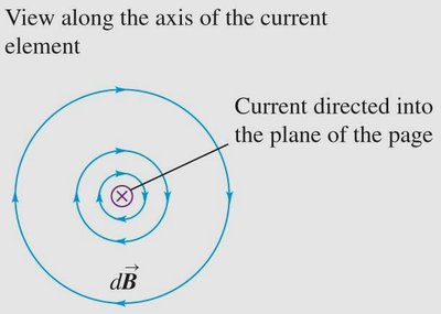
A current, which is a group of moving charges, produces a magnetic field. The field at any point is the vector sum of the fields produced by each infinitesimal segment of the current.
Field Lines: The magnetic field lines around a straight current-carrying wire are circles centered on the wire and lie in planes perpendicular to the wire.
Magnitude: The strength of the field is constant on any circle centered on the wire.
Biot-Savart Law
Mathematical Description of Magnetic Fields
The Biot-Savart Law provides a quantitative method to calculate the magnetic field produced at a point by a current-carrying wire.
Law Statement: The magnetic field dB at point P due to a small segment ds of current I is: where \( \mu_0 \) is the permeability of free space, \( \theta \) is the angle between ds and the vector r from ds to P, and r is the distance from ds to P.
Vector Form:
Total Field: The total magnetic field is found by integrating over the entire current path:
Permeability of Free Space:
Worked Examples: Magnetic Field Calculations
Example 1: Straight Wire
For a thin straight wire of length L carrying constant current I, the total magnetic field at point P is calculated using the Biot-Savart Law. The field points out of the page and its magnitude is:
For L → ∞, , where a is the perpendicular distance from the wire to point P.
Example 2: Wire with Circular Arc
For a wire consisting of two straight segments and a circular arc of radius R subtending angle \( \theta \), only the arc contributes to the field at the center:
Direction of Magnetic Field: QuickCheck Example
Field Direction Above a Wire
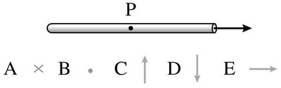
When observing a point above a current-carrying wire, the direction of the magnetic field at that point can be determined using the right-hand rule.
Ampère’s Law
Integral Law for Magnetic Fields
Ampère’s Law relates the integrated magnetic field around a closed loop to the total current passing through the loop. It is especially useful for calculating fields in symmetric situations.
Law Statement: where I_{enc} is the total current enclosed by the path.
Application: Choose a path that reflects the symmetry of the problem and where B is constant along the path.
Direction: Use the right-hand rule to determine the direction of B and the sign of the enclosed current.
Using Ampère’s Law: Steps
Choose an integration path reflecting symmetry.
Ensure B is constant along the path.
Path must pass through the point of interest.
Determine direction of B using symmetry.
Evaluate the path integral.
Calculate the enclosed current, considering current density if necessary.
Example: Comparison of Loops
For two loops surrounding the same current, the integral \( \int \vec{B} \cdot d\vec{l} \) is the same for both, as dictated by Ampère’s Law.
Key Concepts for Week 7
Magnetic field of a moving charge
Biot-Savart Law
Ampère’s Law
Adding magnetic fields
Force between current-carrying wires
Magnetic fields in coils and solenoids
Diamagnetism, Paramagnetism, Ferromagnetism
Additional info: The notes above expand on the original brief points, providing definitions, formulas, and examples for each concept. Images are included only where they directly clarify the explanation of torque, dipole moment, field lines, and field direction.
