 Back
BackMagnetic Flux and Faraday’s Law of Induction – Study Notes
Study Guide - Smart Notes
 Tailored notes based on your materials, expanded with key definitions, examples, and context.
Magnetic Flux and Faraday’s Law of Induction
Introduction
This chapter explores the principles of electromagnetic induction, focusing on how changing magnetic fields can induce electric currents. Key concepts include magnetic flux, Faraday’s law, Lenz’s law, and their applications in devices such as generators, motors, and transformers.
Induced Electromotive Force (EMF)
Faraday’s Experiment
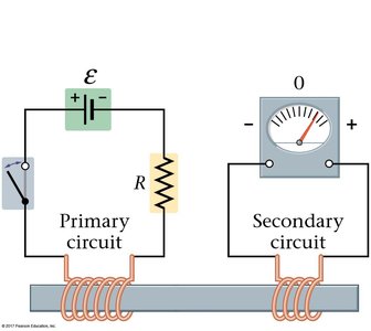
Faraday’s experiment demonstrated that a changing magnetic field can induce an electromotive force (emf) in a nearby circuit. When the current in the primary coil changes, the magnetic field in the iron bar changes, inducing a current in the secondary coil. However, if the current is steady, no emf is induced in the secondary coil.
Key Point: Induced emf occurs only when the magnetic field is changing.
Key Point: The magnitude of the induced current is proportional to the rate of change of the magnetic field.
Magnetic Flux
Definition and Calculation
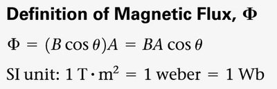
Magnetic flux (Φ) quantifies the amount of magnetic field passing through a given area. It is crucial for calculating induced emf.
Formula:
SI Unit: 1 tesla·meter2 = 1 weber (Wb)
Variables: B = magnetic field strength, A = area, θ = angle between B and the normal to the area.
Faraday’s Law of Induction
Statement and Formula
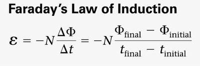
Faraday’s law states that an emf is induced in a circuit only when the magnetic flux through the circuit changes with time. The induced emf is proportional to the rate of change of magnetic flux and the number of loops in the coil.
Formula:
Negative Sign: Indicates the direction of the induced emf opposes the change in flux (Lenz’s law).
Lenz’s Law
Direction of Induced Current
Lenz’s law determines the direction of the induced current: it always opposes the change in magnetic flux that caused it. This is a consequence of the conservation of energy.
Increasing Magnetic Field: Induced current creates a field in the opposite direction.
Decreasing Magnetic Field: Induced current creates a field in the same direction as the original field.
Applications of Faraday’s Law
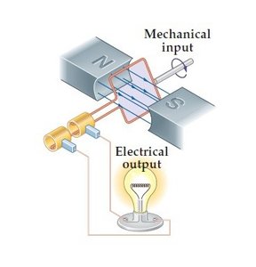
Electric Generators
Electric generators convert mechanical energy into electrical energy by rotating a coil in a magnetic field, inducing a sinusoidal emf.
Formula for Maximum emf:
Increasing Rotation Rate: Increases the maximum output voltage.
Electric Motors
Electric motors operate on the reverse principle: they use the torque on a current-carrying loop in a magnetic field to produce mechanical energy.
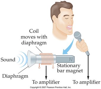
Microphone Example
Dynamic microphones use electromagnetic induction. Sound waves move a diaphragm attached to a coil, which moves relative to a stationary magnet, inducing a current that is amplified and converted to sound.
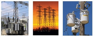
Transformers
Transformers use electromagnetic induction to change the voltage of alternating current (AC). They consist of primary and secondary coils wound around a common core. The voltage ratio is proportional to the ratio of the number of turns in each coil.
Transformer Equation:
Power Conservation: (assuming ideal transformer)
Inductance and RL Circuits
Inductance
Inductance (L) is a property of a coil that quantifies its ability to induce an emf in itself when the current changes. The inductance of a solenoid is given by:
Formula:
Variables: N = number of turns, A = cross-sectional area, l = length, μ₀ = permeability of free space.
RL Circuits
When a switch in an RL circuit is closed, the current increases gradually due to the back emf induced by the inductor. The time constant for the circuit is , where R is resistance.
Energy Stored in a Magnetic Field
Energy is stored in the magnetic field of an inductor. The energy stored is:
Formula:
Summary Table: Key Equations and Concepts
Concept | Equation | Notes |
|---|---|---|
Magnetic Flux | SI unit: Weber (Wb) | |
Faraday’s Law | Induced emf | |
Lenz’s Law | Direction opposes change | Conservation of energy |
Inductance (Solenoid) | Depends on geometry | |
Energy in Inductor | Magnetic energy storage | |
Transformer | AC only |
Practice Problems
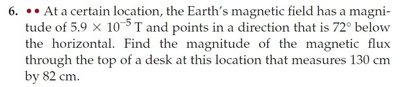
Example 1: Calculate the magnetic flux through a desk (see image_19 for problem statement).
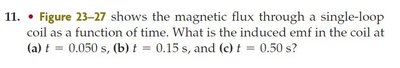
Example 2: Use the graph of magnetic flux vs. time to determine when the induced emf is greatest (see image_23).

Summary
A changing magnetic field induces an emf and possibly a current in a circuit.
The magnitude of the induced emf depends on the rate of change of magnetic flux.
Lenz’s law ensures the induced current opposes the change in flux.
Applications include generators, motors, microphones, and transformers.
