 Back
BackMagnetic Flux and Faraday’s Law of Induction – Study Notes
Study Guide - Smart Notes
 Tailored notes based on your materials, expanded with key definitions, examples, and context.
Chapter 23: Magnetic Flux and Faraday’s Law of Induction
Introduction
This chapter explores the fundamental principles of electromagnetic induction, focusing on how changing magnetic fields induce electromotive force (emf) and current in circuits. Key concepts include magnetic flux, Faraday’s law, Lenz’s law, and their applications in devices such as generators, motors, and transformers.
Induced Electromotive Force (emf)
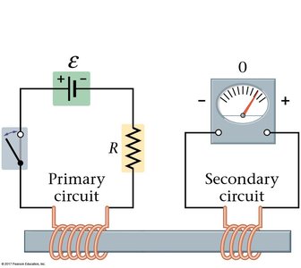
Faraday’s Experiment
Faraday’s experiment demonstrated that a changing current in a primary coil induces a current in a secondary coil, but only while the current is changing. This effect is the basis for electromagnetic induction.
Induced emf occurs only when the magnetic field through a circuit changes with time.
The magnitude of the induced current is proportional to the rate of change of the magnetic field.
Magnetic Flux
Definition and Calculation
Magnetic flux quantifies the amount of magnetic field passing through a given area. It is essential for calculating induced emf.
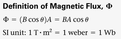
Magnetic flux (\( \Phi \)) is defined as:
Where B is the magnetic field strength, A is the area, and \( \theta \) is the angle between the field and the normal to the area.
SI unit: 1 tesla·meter2 = 1 weber (Wb)
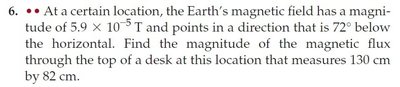
Example Calculation
To change the magnetic flux through a loop, you can move the magnet, tilt the loop, or change the loop area.
Faraday’s Law of Induction
Statement and Equation
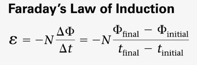
Faraday’s law states that an emf is induced in a circuit when the magnetic flux through the circuit changes with time.
The induced emf is given by:
N is the number of turns in the coil.
The negative sign indicates the direction of the induced emf opposes the change in flux (Lenz’s law).
Applications
Electric guitar pickups and tape recorders operate based on Faraday’s law.
Lenz’s Law
Statement and Physical Meaning
Lenz’s law determines the direction of the induced current: it always opposes the change in magnetic flux that caused it.
If the magnetic field is increasing, the induced current creates a field in the opposite direction.
If the magnetic field is decreasing, the induced current creates a field in the same direction.
Examples
When a north pole of a magnet moves toward a loop, the induced current is counterclockwise to oppose the increase in flux.
If the magnet moves parallel to the loop (no change in flux), no current is induced.
Mechanical Work and Electrical Energy
Energy Conversion
Mechanical work done to move a conductor in a magnetic field is converted into electrical energy (induced emf and current).
The power delivered by the external force equals the electrical power output.
Generators and Motors
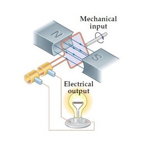
Electric Generators
Generators convert mechanical energy into electrical energy by rotating coils in a magnetic field, inducing a sinusoidal emf.
The maximum emf is given by:
Where N is the number of turns, B is the magnetic field, A is the area, and \omega is the angular velocity.
Electric Motors
Motors operate on the reverse principle: they use the torque on a current-carrying loop in a magnetic field to produce mechanical motion.
Inductance and RL Circuits
Inductance
Inductance is the property of a coil that quantifies how much emf is induced for a given rate of change of current.
Inductance of a solenoid:
Where \mu_0 is the permeability of free space, N is the number of turns, A is the cross-sectional area, and l is the length.
RL Circuits
When a switch is closed, the current increases gradually due to the back emf in the inductor.
The time constant for an RL circuit is:
Where L is inductance and R is resistance.
Energy Stored in a Magnetic Field
Energy in an Inductor
The energy stored in an inductor’s magnetic field is given by:
Energy density in a magnetic field:
Transformers
Principle and Equations
Transformers use electromagnetic induction to change the voltage of alternating current (AC).
Transformer equation:
Where V_s and V_p are the secondary and primary voltages, and N_s and N_p are the number of turns in the secondary and primary coils, respectively.
Power conservation:
Summary Table: Key Equations and Concepts
Concept | Equation | Notes |
|---|---|---|
Magnetic Flux | SI unit: weber (Wb) | |
Faraday’s Law | Induced emf | |
Inductance (Solenoid) | Depends on geometry | |
Energy in Inductor | Magnetic energy storage | |
Transformer | AC only |
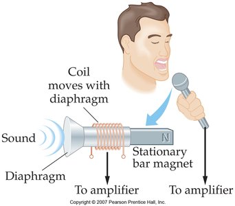
Example: Microphone as an Application of Faraday’s Law
Dynamic microphones use electromagnetic induction to convert sound waves into electrical signals. The diaphragm moves a coil in the presence of a stationary magnet, inducing a current proportional to the sound.
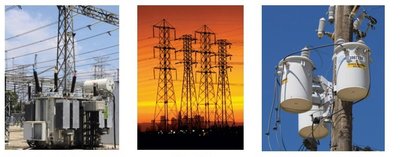
Example: Power Transmission and Transformers
Transformers are essential for efficient power transmission over long distances, allowing voltage to be increased or decreased as needed.
Additional info:
All equations are provided in LaTeX format for clarity.
Images are included only when directly relevant to the explanation.
