 Back
BackPhysics 1302W Practice Quiz #3 Study Guidance
Study Guide - Smart Notes
 Tailored notes based on your materials, expanded with key definitions, examples, and context.
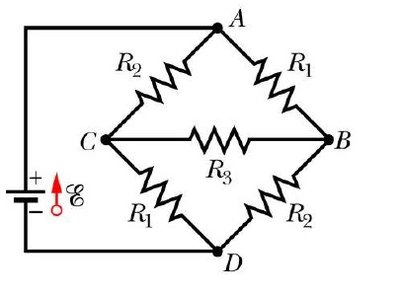
Q1. For the circuit shown, with EMF , , , and , find the following potential differences: (a) , (b) , (c) . First, determine how the currents through the three resistors are related, then construct two Kirchhoff voltage loops to solve for these currents.
Background
Topic: DC Circuits, Kirchhoff's Rules
This question tests your ability to analyze a multi-loop circuit using Kirchhoff's voltage and current laws, and to relate currents through different branches to find potential differences.
Key Terms and Formulas
Kirchhoff's Current Law: The sum of currents entering a junction equals the sum leaving.
Kirchhoff's Voltage Law: The sum of potential differences around any closed loop is zero.
Ohm's Law:
Step-by-Step Guidance
Assign current variables to each branch (e.g., through , through , through ). Use the symmetry and the information given to relate these currents.
Apply Kirchhoff's Current Law at the junctions to write equations relating , , and .
Construct two independent Kirchhoff voltage loops that include the battery and the resistors. Write out the loop equations using and the resistances.
Express the potential differences , , and in terms of the currents and resistances using Ohm's Law.
Try solving on your own before revealing the answer!
Final Answer:
After solving the system of equations, you find the currents and use Ohm's Law to compute the requested potential differences:
(a) (b) (c)
These results follow from correctly applying Kirchhoff's rules and Ohm's Law to the circuit.
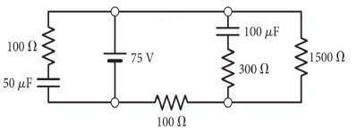
Q2. The circuit below has been running for a very long time. What is the magnitude of voltage on the 100 μF capacitor?
Background
Topic: DC Circuits, Capacitors in Steady State
This question tests your understanding of how capacitors behave in circuits after a long time (steady state), and how to use series and parallel rules to find voltages.
Key Terms and Formulas
Capacitor in steady state: Acts as an open circuit (no current flows through it).
Voltage across capacitor:
Series and parallel rules for resistors and capacitors.
Step-by-Step Guidance
Identify which branches contain capacitors and which contain resistors.
After a long time, replace each capacitor with an open circuit and redraw the circuit.
Determine the voltage drop across the branch containing the 100 μF capacitor using series and parallel rules.
Set up the equations for voltage division across the resistors in the branch with the capacitor.
Try solving on your own before revealing the answer!
Final Answer: 65 V
The voltage across the 100 μF capacitor is 65 V, found by analyzing the circuit in steady state and using voltage division.
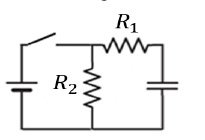
Q3. In the circuit shown, both resistors have a resistance of 1 Ω, the battery has an EMF of 1 V, and the capacitor has a capacitance of 1.0 nC. Initially, the capacitor is uncharged. What is the current through the resistor R1: (a) the instant the switch is closed and (b) a very long time after the switch is closed?
Background
Topic: RC Circuits, Transient and Steady-State Analysis
This question tests your understanding of how current changes in an RC circuit at different times: immediately after closing the switch and after a long time.
Key Terms and Formulas
RC Circuit: A circuit with resistors and capacitors.
Initial current: Capacitor acts as a short circuit (uncharged).
Steady-state current: Capacitor acts as an open circuit (fully charged).
Current:
Step-by-Step Guidance
At , consider the capacitor as a wire (short circuit). Find the equivalent resistance and calculate the initial current through .
After a long time, the capacitor is fully charged and acts as an open circuit. Find the new equivalent resistance and calculate the current through .
Set up the equations for both cases using Ohm's Law.
Compare the two scenarios and write the expressions for the current in each case.
Try solving on your own before revealing the answer!
Final Answer: (a) 1A and (b) 0
At the instant the switch is closed, the current through is 1A. After a long time, the current is 0 because the capacitor blocks the current.
Q4. A wire of length L and carrying a current I is bent into a square loop to form a magnetic dipole. This dipole is then oriented in a uniform magnetic field of magnitude B such that the dipole is in its lowest energy state. What is the value of the dipole’s energy with this orientation?
Background
Topic: Magnetic Dipoles, Energy in Magnetic Fields
This question tests your understanding of the energy of a magnetic dipole in a uniform magnetic field, especially in its lowest energy state.
Key Terms and Formulas
Magnetic dipole moment:
Area of square loop: (if loop is made from wire of length L)
Energy: (lowest energy state)
Step-by-Step Guidance
Calculate the area of the square loop formed by the wire.
Find the magnetic dipole moment using .
Write the expression for the energy of the dipole in the lowest energy state.
Substitute the values for , , and into the energy formula.
Try solving on your own before revealing the answer!
Final Answer:
The lowest energy state corresponds to the dipole aligned with the field, so with .
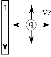
Q5. A positive point charge moves with a velocity next to a long, straight wire carrying a current downward. Because of the charge’s motion, there exists a force on the charge in the downward direction, parallel to the current’s direction. The charge could be moving:
Background
Topic: Magnetic Forces on Moving Charges
This question tests your understanding of the direction of the magnetic force on a moving charge near a current-carrying wire, using the right-hand rule.
Key Terms and Formulas
Magnetic force:
Right-hand rule for cross product direction.
Step-by-Step Guidance
Determine the direction of the magnetic field produced by the wire using the right-hand rule.
For each possible velocity direction, use the right-hand rule to find the direction of the force on the positive charge.
Identify which velocity direction results in a force parallel to the current (downward).
Write out the reasoning for the correct answer.
Try solving on your own before revealing the answer!
Final Answer: (A) to the left
If the charge moves to the left, the magnetic force points downward, parallel to the current direction.
Q6. What is the value of for the Amperian path drawn in the figure, which shows three long, straight current-carrying wires (flowing in the directions labeled) looking end-on? Note the contour’s direction.
Background
Topic: Ampère's Law, Magnetic Fields from Currents
This question tests your ability to apply Ampère's Law to a path enclosing multiple wires, considering the direction of current and the contour.
Key Terms and Formulas
Ampère's Law:
Direction of contour and sign of enclosed currents.
Step-by-Step Guidance
Identify which wires are enclosed by the Amperian path and their current directions.
Sum the enclosed currents, assigning positive or negative signs based on direction relative to the contour.
Apply Ampère's Law to write the expression for .
Substitute the values and signs for the enclosed currents.
Try solving on your own before revealing the answer!
Final Answer:
The sum of the enclosed currents, considering their directions, gives , so the integral is .
