 Back
BackPhysics 1302W Quiz #3 Study Guidance
Study Guide - Smart Notes
 Tailored notes based on your materials, expanded with key definitions, examples, and context.
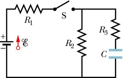
Q1. In the circuit below, E = 12 V, R1 = R2 = R3 = 1.0 MΩ, and C = 10 µF. The capacitor is initially uncharged and the wires are ideal. Switch S is suddenly closed at t = 0.
(A) Calculate the current in each of the three resistors immediately after the switch is closed (t = 0).
(B) Calculate the current in each of the three resistors a long time after the switch is closed (t = ∞).
(C) Determine the potential difference across the capacitor at long times.
Background
Topic: RC Circuits and Transient Analysis
This problem tests your understanding of how currents and voltages change in a circuit containing resistors and a capacitor, both immediately after a switch is closed and after a long time has passed.
Key Terms and Formulas
Ohm's Law:
Capacitor charging equation: and , where
Kirchhoff's Rules: Sum of voltages around a loop is zero; sum of currents into a node is zero.
Capacitance:
Step-by-Step Guidance
Immediately after the switch is closed (), the capacitor behaves like a short circuit (uncharged, so ). Analyze the circuit as if the capacitor is just a wire.
Draw the equivalent circuit for : The current from the battery splits between the two branches (one with , one with and the capacitor).
Apply Kirchhoff's rules to find the current through each resistor. Use and the fact that the total resistance in each branch can be calculated.
For , the capacitor is fully charged and acts as an open circuit (no current flows through and ). Redraw the circuit and recalculate the currents.
To find the potential difference across the capacitor at long times, use the voltage divider rule and the fact that the capacitor is in parallel with .
Try solving on your own before revealing the answer!
Final Answer:
(A) At , the current through is A, through is A, and through is A.
(B) At , the current through and is A, and through is $0$.
(C) The potential difference across the capacitor at long times is $12$ V.
These results follow from applying Kirchhoff's rules and considering the behavior of the capacitor at different times.
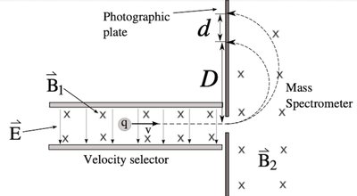
Q2. A velocity selector/mass spectrometer combo is used to separate a beam of boron-10 and boron-11 isotopes. Boron-10 isotopes have mass of 10u and boron-11 have mass of 11u. Both are singly ionized (charge ). The vertical distance from where boron-10 enters to where it hits the plate is cm. The magnetic fields of the velocity selector ( T) and mass spectrometer ( T) both point into the page.
(A) For a charged particle moving in a magnetic field, what is the radius of its circle in terms of its charge, mass, velocity, and the magnetic field strength?
(B) What is the distance between where boron-10 and boron-11 hit the photographic plate?
(C) Determine the speed of the isotopes that enter the mass spectrometer.
(D) The velocity selector is a section where the electric and magnetic forces cancel for one specific velocity. Determine the magnitude of the electric field in this velocity selector.
Background
Topic: Mass Spectrometry, Lorentz Force, and Velocity Selector
This problem tests your understanding of how charged particles move in electric and magnetic fields, and how mass spectrometers separate isotopes based on their mass-to-charge ratio.
Key Terms and Formulas
Radius of circular motion:
Lorentz force: (for perpendicular velocity and field)
Velocity selector:
Atomic mass unit: kg
Charge of electron/proton: C
Step-by-Step Guidance
For part (A), recall that the centripetal force required for circular motion is provided by the magnetic force: .
Rearrange to solve for the radius in terms of , , , and .
For part (B), use the radius formula for both isotopes and calculate the difference in their impact positions on the plate.
For part (C), use the velocity selector condition: , but first determine what must be for the particles to pass through.
For part (D), set the electric and magnetic forces equal and solve for using the known and .
Try solving on your own before revealing the answer!
Final Answer:
(A)
(B) , where and are the radii for boron-10 and boron-11.
(C)
(D)
These answers use the relationships between mass, charge, velocity, and field strength for charged particles in magnetic and electric fields.
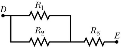
MC1. In the figure provided, the resistors have the following values: R1 = R2 = 4.00 Ω and R3 = 2.50 Ω. What is the equivalent resistance between points D and E?
Background
Topic: Series and Parallel Resistor Combinations
This question tests your ability to calculate equivalent resistance in a circuit with both series and parallel components.
Key Terms and Formulas
Resistors in series:
Resistors in parallel:
Step-by-Step Guidance
Identify which resistors are in parallel and which are in series between points D and E.
Calculate the equivalent resistance of the parallel section ( and ).
Add the resistance of in series to the parallel combination.
Try solving on your own before revealing the answer!
Final Answer:
The parallel combination of and is , and adding gives the total resistance.
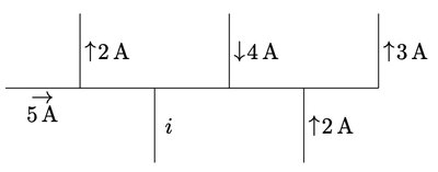
MC2. Using Kirchhoff’s rules, determine the magnitude and direction of the unknown current i.
Background
Topic: Kirchhoff’s Current Law (KCL)
This question tests your ability to apply Kirchhoff’s rules to determine unknown currents at a junction.
Key Terms and Formulas
Kirchhoff’s Current Law: The sum of currents entering a junction equals the sum leaving.
Step-by-Step Guidance
Identify all currents entering and leaving the junction where is located.
Write the equation for the sum of currents at the junction, assigning positive and negative signs based on direction.
Solve for using the values given for the other currents.
Try solving on your own before revealing the answer!
Final Answer:
A, direction is upward ()
By summing the currents at the junction, you find the unknown current and its direction.
MC3. A wire, bent into a circular loop with diameter d, carries a current I. This loop is then placed in a region with a uniform magnetic field of magnitude B such that the dipole moment of the loop is in the same direction as that of the field. How much energy is required to rotate the loop 180° in this field, flipping the direction of its dipole moment?
Background
Topic: Magnetic Dipole Energy
This question tests your understanding of the energy required to flip a magnetic dipole in a uniform magnetic field.
Key Terms and Formulas
Magnetic dipole moment:
Area of a circle:
Energy difference: (for flipping 180°)
Step-by-Step Guidance
Calculate the magnetic dipole moment for the loop.
Determine the initial and final energy of the dipole in the field.
Find the energy difference required to flip the dipole 180°.
Try solving on your own before revealing the answer!
Final Answer:
This is the energy required to flip the loop in the magnetic field.
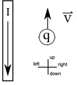
MC4. A positive point charge moves up with a velocity next to a long, straight wire carrying a current downward. At this instant, what is the direction of the force on the charge?
Background
Topic: Magnetic Force on a Moving Charge
This question tests your ability to use the right-hand rule to determine the direction of the magnetic force on a moving charge near a current-carrying wire.
Key Terms and Formulas
Magnetic force:
Right-hand rule: Thumb in direction of , fingers in direction of , palm points in direction of force for positive charge.
Step-by-Step Guidance
Determine the direction of the magnetic field produced by the wire at the location of the charge.
Use the right-hand rule to find the direction of the force on the positive charge.
Try solving on your own before revealing the answer!
Final Answer:
The force is directed out of the page.
Using the right-hand rule, the cross product of velocity and magnetic field gives the force direction.
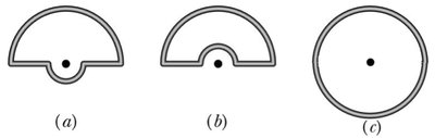
MC5. The figure shows three circuits consisting of straight radial lengths and concentric circular arcs (half-circles of radii r and 3r). The circuits carry the same current. Which among these configurations will produce the largest magnitude magnetic field at the center of curvature (the dot)?
Background
Topic: Magnetic Field from Current-Carrying Arcs
This question tests your understanding of how the geometry of current-carrying wires affects the magnetic field at a specific point.
Key Terms and Formulas
Magnetic field at center of arc: for arc subtending angle
Step-by-Step Guidance
Analyze each configuration to determine the contribution of each arc to the magnetic field at the center.
Compare the fields produced by arcs of different radii and angles.
Try solving on your own before revealing the answer!
Final Answer:
Configuration (c) produces the largest magnetic field at the center.
The field is strongest for the arc with the smallest radius and largest angle.
