 Back
BackPhysics II Exam Study Guide: Magnetism, Circuits, and Electromagnetic Waves
Study Guide - Smart Notes
 Tailored notes based on your materials, expanded with key definitions, examples, and context.
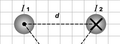
Q7. Field of a Long Wire: The figure shows two long, parallel current-carrying wires. The wires carry equal currents I₁ = I₂ = 20 A in the directions indicated and are located a distance d = 0.5 m apart. Calculate the magnitude and direction of the magnetic field at the point P that is located an equal distance d from each wire. (μ₀ = 4π × 10⁻⁷ T·m/A)
Background
Topic: Magnetic Field Due to Parallel Currents
This question tests your understanding of the magnetic field produced by long, straight, current-carrying wires and how to use the superposition principle to find the net field at a point due to multiple wires.
Key Terms and Formulas
Magnetic field due to a long straight wire at distance r:
Superposition principle: The net magnetic field is the vector sum of the fields from each wire.
Right-hand rule: Determines the direction of the magnetic field around a current-carrying wire.
Step-by-Step Guidance
Calculate the magnetic field at point P due to one wire using , where and .
Determine the direction of the magnetic field at P from each wire using the right-hand rule. Consider the direction of the currents (into/out of the page).
Since P is equidistant from both wires, the magnitudes of the fields from each wire will be equal. Draw a vector diagram to show the directions of the two fields at P.
Use vector addition to find the net magnetic field at P. Consider the angle between the two field vectors (they may add or subtract depending on their directions).
Try solving on your own before revealing the answer!
Final Answer: 8 μT upward
The field from each wire at P is , and the directions add constructively upward, giving a total of upward.
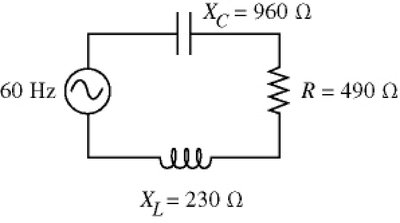
Q14. LRC Series Circuits: The 60-Hz ac source of a series circuit has a voltage amplitude of 120 V. The resistance, capacitive reactance, and inductive reactance are as shown in the figure. What is the rms current in the circuit?
Background
Topic: AC Circuits – Impedance and RMS Current
This question tests your ability to analyze an LRC (inductor-resistor-capacitor) series circuit, calculate the total impedance, and determine the rms current using the given voltage amplitude.
Key Terms and Formulas
Impedance of a series LRC circuit:
RMS current:
Relationship between peak and rms voltage:
Step-by-Step Guidance
Identify the given values: , , , .
Calculate the total impedance using .
Convert the voltage amplitude to rms voltage: V.
Set up the formula for rms current: .
Try solving on your own before revealing the answer!
Final Answer: 0.097 A
After calculating the impedance and using the rms voltage, the rms current is approximately 0.097 A.
