 Back
BackPhysics Study Guide: Collisions, Rotational Dynamics, Thermodynamics, and Statics
Study Guide - Smart Notes
 Tailored notes based on your materials, expanded with key definitions, examples, and context.
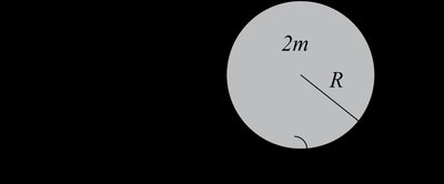
Q1. A small ball of mass 3m is traveling on a frictionless plane with speed 2v₀ toward a uniform disk of mass 2m and radius R (I = ½MR² with M = 2m) that is moving to the left with a center of mass velocity of v₀. The disk is not rotating before the collision. The ball just grazes the edge of the disk and is caught in a massless catcher at the disk’s edge and sticks in it. With y = 0 at the bottom edge of the disk and positive toward the top of the page, what is the y coordinate of the center of mass of the system of ball and disk after the collision?
Background
Topic: Center of Mass in Collisions
This question tests your understanding of how to calculate the center of mass for a composite system after a collision, using mass-weighted positions.
Key formula:
= mass of ball (3m)
= y-position of ball (at the edge, y = R)
= mass of disk (2m)
= y-position of disk's center (y = ?)
Step-by-Step Guidance
Identify the masses and their y-positions: The ball is at y = R, the disk's center is at y = ? (typically at y = R/2 if the disk is vertical, but check the diagram).
Write the center of mass formula for the two-object system.
Plug in the values for masses and positions, but do not compute the final value yet.
Try solving on your own before revealing the answer!
Final Answer:
The center of mass is found by mass-weighting the y-positions of the ball and disk.
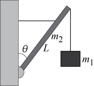
Q2. A box of mass m₁ hangs from the end of a uniform beam of length L and mass m₂, which is supported at an angle θ away from the vertical by a freely pivoting hinge at its bottom-most point and by a rope pulling precisely horizontally on the beam at a distance d from the hinge as measured along the beam. Draw a free-body diagram of the beam, labeling all the forces and the locations at which the forces are acting on the beam.
Background
Topic: Statics and Free-Body Diagrams
This question tests your ability to identify and label forces acting on a rigid body in equilibrium.
Key Terms:
Tension () in the rope
Weight of the box ()
Weight of the beam ()
Hinge reaction forces (horizontal and vertical components)
Step-by-Step Guidance
Draw the beam and indicate the pivot point at the bottom.
Label the weight of the beam acting at its center of mass (midpoint).
Label the weight of the box acting at the end of the beam.
Label the tension force from the rope acting horizontally at distance d from the hinge.
Label the hinge reaction forces (both horizontal and vertical components).
Try solving on your own before revealing the answer!
Final Answer: See diagram for labeled forces.
The free-body diagram should show all forces acting at their correct locations and directions.
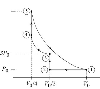
Q3. An ideal gas (number of moles = n) with adiabatic index γ = 2 is taken through a cycle as shown in the figure. The cycle proceeds as follows: 1–2 is an isobaric compression to , 2–3 is an isochoric process with , 3–4 is an isothermal compression to , 4–5 is an isochoric heating process, 5–1 is an adiabatic expansion back to . From the information above, find the missing values of P (in terms of ) and T (in terms of ). Make sure to show ALL your work.
Background
Topic: Thermodynamic Cycles and State Variables
This question tests your ability to use the ideal gas law and process-specific relationships to determine pressures and temperatures at each state in a cycle.
Key formula:
Isobaric: constant, changes
Isochoric: constant, changes
Isothermal: constant, constant
Adiabatic: constant
Step-by-Step Guidance
For each state, use the process type to relate , , and using the ideal gas law.
For isobaric compression (1–2), , ,
For isochoric (2–3), , ,
For isothermal (3–4), , ,
Try solving on your own before revealing the answer!
Final Answer: See completed table for and values.
Each state is determined using the ideal gas law and the constraints of the process.
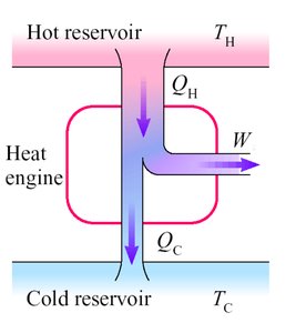
Q4. Four different heat engines are claimed to be operating on unspecified thermodynamic cycles and to have the performances specified in the table below. Your job is to identify whether or not each engine below is physically possible or not. Show whether or not the engine obeys the first and second laws of thermodynamics.
Background
Topic: Thermodynamics – Heat Engines, First and Second Laws
This question tests your understanding of energy conservation and entropy in heat engines.
Key Terms:
= heat absorbed from hot reservoir
= heat expelled to cold reservoir
= work output
First Law:
Second Law: Efficiency
Step-by-Step Guidance
For each engine, check if (energy conservation).
Calculate the efficiency and compare to Carnot efficiency .
Determine if the engine violates either law.
Try solving on your own before revealing the answer!
Final Answer: See table for possible/impossible engines and reasons.
Engines are possible only if they obey both the first and second laws.
