 Back
BackPotentiometers, EMF Comparison, and Potential Divider Circuits – SW2
Study Guide - Smart Notes
 Tailored notes based on your materials, expanded with key definitions, examples, and context.
Q1. To make a potentiometer, a driver cell of e.m.f. 4.0 V is connected across a 1.00 m length of resistance wire.
Background
Topic: Potentiometers and Potential Difference
This question tests your understanding of how a potentiometer works, how potential difference is distributed along a uniform resistance wire, and how to use a potentiometer to measure unknown e.m.f.s.
Key Terms and Formulas
Potential difference (p.d.): The work done per unit charge to move a charge between two points.
Uniform resistance wire: The potential difference is proportional to the length of wire.
Formula: and (for a uniform wire)
Step-by-Step Guidance
Calculate the potential difference across each 1 cm of wire by dividing the total e.m.f. by the total length (in cm).
Set up a proportion to find the length of wire that would have a p.d. of 1.0 V across it.
For part (b), use the proportionality between length and e.m.f. to estimate the unknown e.m.f. based on the balance length.
For part (c), use the standard cell's balance length to set up a ratio and solve for the unknown e.m.f. more accurately.
Try solving on your own before revealing the answer!
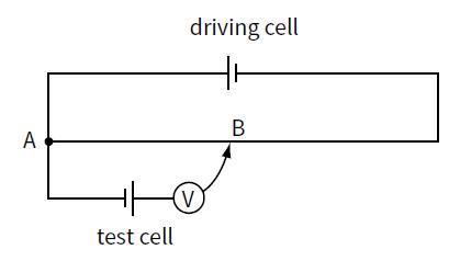
Q2. A student is asked to compare the e.m.f.s of a standard cell and a test cell. He sets up the circuit shown in the figure using the test cell.
Background
Topic: Potentiometer – Comparing EMFs
This question explores how a potentiometer can be used to compare the e.m.f.s of two cells and the importance of circuit setup for achieving a balance point.
Key Terms and Formulas
Balance point: The point along the wire where the potential difference equals the e.m.f. of the test cell, resulting in zero current through the galvanometer or voltmeter.
Formula for comparing e.m.f.s:
Step-by-Step Guidance
Explain why a balance point cannot be found if the test cell's e.m.f. is greater than the driver cell's p.d. across the wire.
Describe what change is needed in the circuit to achieve a balance (e.g., swapping cells or adjusting the driver cell).
State how the student would recognize the balance point (e.g., voltmeter reads zero).
Set up the ratio using the measured balance lengths for the test and standard cells to calculate the unknown e.m.f.
Try solving on your own before revealing the answer!
Q3. This diagram shows two circuits that could be used to act as a dimmer switch for a lamp.
Background
Topic: Series and Parallel Circuits, Resistance, and Power
This question examines the advantages of different circuit arrangements for controlling lamp brightness, and how to calculate resistance from power and voltage ratings.
Key Terms and Formulas
Power:
Ohm's Law:
Resistance from power and voltage:
Step-by-Step Guidance
Compare the two circuits and explain why one might be preferable (e.g., energy efficiency, control range).
Use the lamp's rating (60 W at 240 V) to calculate its resistance at normal operating temperature.
Discuss how the resistance of the filament at room temperature would compare to its resistance when hot, and explain why.
Try solving on your own before revealing the answer!
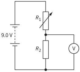
Q4. This circuit shows a potential divider. The battery has negligible internal resistance and the voltmeter has infinite resistance.
Background
Topic: Potential Divider Circuits
This question tests your understanding of how a potential divider works and how voltmeter readings change with resistance adjustments.
Key Terms and Formulas
Potential divider formula:
Effect of voltmeter resistance: When the voltmeter is not ideal, it affects the total resistance and voltage division.
Step-by-Step Guidance
Explain how increasing the variable resistor affects the voltmeter reading, using the potential divider formula.
Given and a voltmeter reading of 2.0 V, set up the equation to solve for the variable resistor's value.
When the voltmeter is replaced with one of finite resistance (2 kΩ), redraw the equivalent circuit and set up the calculation for the new voltmeter reading.
Try solving on your own before revealing the answer!
Q5. A potentiometer, which consists of a driving cell connected to a resistance wire of length 100 cm, is used to compare the resistances of two resistors.
Background
Topic: Potentiometer – Comparing Resistances and Uncertainty Analysis
This question involves using a potentiometer to compare resistances and calculate uncertainties in measurements and ratios.
Key Terms and Formulas
Potentiometer: Used to compare unknown resistances by measuring balance lengths.
Uncertainty: The range within which the true value is expected to lie.
Ratio of resistances: and
Propagation of uncertainty: Combine uncertainties in measurements to find uncertainty in calculated ratios.
Step-by-Step Guidance
Draw a labeled diagram showing how the potentiometer is set up to compare two resistors.
Calculate the total uncertainty in the balance length for by combining the individual uncertainties.
Use the measured balance lengths to set up the ratio and calculate its value.
Rearrange the ratio to solve for and set up the calculation.
Determine how to calculate the uncertainty in using the uncertainties in the measured lengths.
Try solving on your own before revealing the answer!
