 Back
BackPractical Circuits Unit Overview
Study Guide - Smart Notes
 Tailored notes based on your materials, expanded with key definitions, examples, and context.
Practical Circuits
Internal Resistance
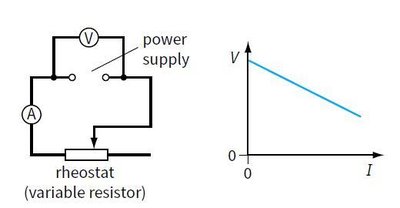
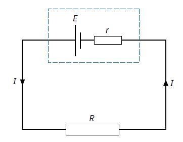
When analyzing real electrical circuits, it is important to consider the internal resistance of power sources such as batteries. Internal resistance causes the voltage available at the terminals of the battery to decrease as the current drawn from the battery increases.
Definition: Internal resistance is the resistance within a battery or other voltage source that causes a drop in the source voltage when current flows.
Effect: The terminal voltage (the voltage you can measure across the battery's terminals) is always less than the battery's electromotive force (e.m.f.) when current is flowing.
Key Equations:
Total e.m.f.:
Terminal voltage:
Lost volts (voltage drop across internal resistance):
Relationship:
Lost Volts: The difference between the e.m.f. and the terminal voltage is called the lost volts, representing energy dissipated inside the battery.
Example: A battery of e.m.f. 5.0 V and internal resistance 2.0 Ω is connected to an 8.0 Ω resistor. The current in the circuit is calculated as:
Total resistance:
Current:
Lost volts:
Terminal p.d.:
Application: When a car's starter motor (which draws a large current) is used, the battery's terminal voltage drops, causing the headlamps to dim.
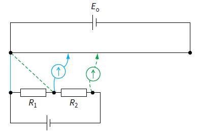
Potential Dividers
A potential divider is a circuit in which two or more resistors are connected in series across a voltage supply. The output voltage is taken across one of the resistors, allowing for a controlled fraction of the input voltage to be used elsewhere in the circuit.
Potential Divider Equation:
Variable Output: By adjusting a variable resistor (such as a rheostat), the output voltage can be varied smoothly from zero up to the supply voltage.
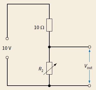
Example: If , is variable from $0, and , then ranges from $0R_2 = 0 (when ).
Potentiometer Circuits
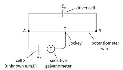
A potentiometer is a device used to compare potential differences or e.m.f.s. It is essentially a long resistance wire with a sliding contact (jockey) that can tap off different voltages along its length.
Operation: The potentiometer is balanced when the galvanometer shows zero deflection, indicating no current flows through it. At this point, the potential difference across the tapped length of wire equals the e.m.f. being measured.
Equation for Unknown e.m.f.: where is the length corresponding to the unknown e.m.f., is the total length, and is the known e.m.f.
Comparing Two e.m.f.s: where and are the balance lengths for and respectively.
Comparing Potential Differences: The ratio of balance lengths is equal to the ratio of the potential differences, and if the same current flows through two resistors, it is also the ratio of their resistances.
Summary Table: Key Equations and Concepts
Concept | Equation | Description |
|---|---|---|
Internal Resistance | Total e.m.f. equals current times total resistance | |
Terminal Voltage | Voltage available at battery terminals | |
Potential Divider | Output voltage across | |
Potentiometer (unknown e.m.f.) | Find unknown e.m.f. using balance length | |
Potentiometer (comparing e.m.f.s) | Ratio of e.m.f.s equals ratio of balance lengths |
