 Back
Ray Optics: Mirrors, Lenses, and Image Formation
Study Guide - Smart Notes
 Tailored notes based on your materials, expanded with key definitions, examples, and context.
Ray Optics
Introduction to Ray Optics
Ray optics, also known as geometric optics, is the study of light propagation in terms of rays. This model is particularly useful for understanding how light interacts with everyday objects such as mirrors and lenses, where the wave nature of light can be neglected.
Light rays travel in straight lines unless they interact with matter.
An object acts as a source of light rays, and the eye sees by focusing a bundle of these rays.
Light rays can cross without affecting each other.
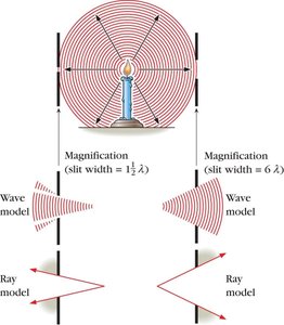
Shadows and the Ray Model
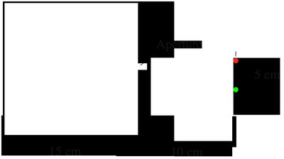
Shadows are a simple application of the ray model. When an object blocks light from a source, it casts a shadow. The size and sharpness of the shadow depend on the size of the light source and the aperture through which light passes.
If the aperture is very small, the images of point-like sources are separated on the screen.
The Law of Reflection
Reflection from Plane Surfaces
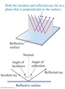
The law of reflection governs how light bounces off reflective surfaces such as mirrors.
The angle of incidence (θi) equals the angle of reflection (θr).
Both the incident and reflected rays lie in the same plane, perpendicular to the surface.
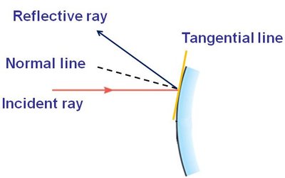
Reflection from Curved Surfaces
Curved mirrors (concave or convex) also obey the law of reflection, but the normal at the point of incidence is perpendicular to the tangent at that point.
Specular vs. Diffuse Reflection
Reflection can occur from smooth (specular) or rough (diffuse) surfaces:
Specular reflection (smooth surface): Light rays reflect in a single direction, producing clear images.
Diffuse reflection (rough surface): Light rays scatter in many directions, making images unclear or invisible.
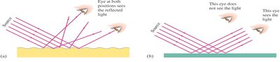
Image Formation by Mirrors
Plane Mirrors
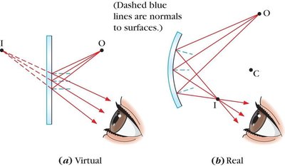
Plane mirrors form images by reflecting light rays. The image formed is called a virtual image because the light rays do not actually pass through the image location; they only appear to do so when extended backward.
Virtual image: Formed when reflected rays diverge; the image appears behind the mirror.
Real image: Formed when reflected rays converge; the image can be projected onto a screen.
Field of View and Mirror Size
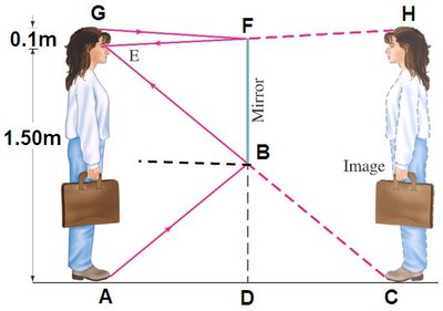
The minimum length of a mirror required to see one's full body depends on the person's height and the position of their eyes relative to the mirror.
Refraction
Law of Refraction (Snell's Law)
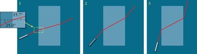
When light passes from one medium to another, its speed changes, causing the light to bend at the interface. This bending is called refraction and is described by Snell's Law:
Snell's Law:
Where and are the indices of refraction of the two media, and and are the angles of incidence and refraction, respectively.
Applications and Examples of Refraction
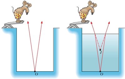
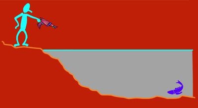
Refraction explains why objects appear distorted or shifted when viewed across media boundaries, such as a stick partially submerged in water.
Dispersion
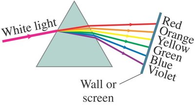
Dispersion occurs because different wavelengths of light refract by different amounts in a material, leading to the separation of white light into its constituent colors (as in a prism).
Total Internal Reflection and Critical Angle
Critical Angle and Total Internal Reflection
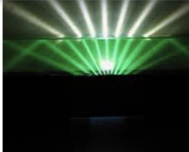
When light travels from a medium with higher refractive index to one with lower refractive index, there exists a critical angle beyond which all light is reflected back into the original medium. This phenomenon is called total internal reflection.
Critical angle: , for
Total internal reflection occurs when the angle of incidence exceeds .
Applications of Total Internal Reflection
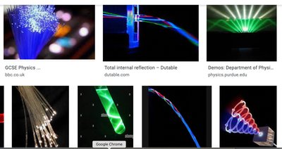
Total internal reflection is used in fiber optics, endoscopes, and other technologies that rely on guiding light efficiently through a medium.
Thin Lenses
Types of Lenses
Thin lenses are classified based on their shape and how they bend light:
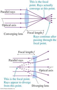
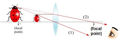
Converging lens (convex): Thicker at the center, brings parallel rays to a focus.
Diverging lens (concave): Thicker at the edges, spreads parallel rays outward.
Focal Point and Ray Diagrams
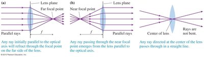
The focal point is the point where parallel rays converge (for a converging lens) or appear to diverge from (for a diverging lens). Ray diagrams help determine the position and nature of images formed by lenses.

The Thin Lens Equation and Magnification
The thin lens equation relates the object distance (), image distance (), and focal length ():
Thin lens equation:
Magnification:
Sign Conventions for Lenses and Mirrors
Sign conventions are essential for correctly applying the lens and mirror equations:
Object distance () and object height () are positive for real objects.
Focal length () is positive for converging lenses/mirrors, negative for diverging.
Image distance () is positive for real images, negative for virtual images.
Magnification () and image height () are positive for upright images, negative for inverted images.
Spherical Mirrors
Concave and Convex Mirrors
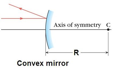
Spherical mirrors are sections of a sphere and can be reflective on the inside (concave) or outside (convex).
Concave mirror: Reflects light inward to a focal point.
Convex mirror: Causes light to diverge as if from a focal point behind the mirror.
Focal Length of Spherical Mirrors
The focal length () of a spherical mirror is related to its radius of curvature ():
For both concave and convex mirrors:
Image Formation by Spherical Mirrors
Ray diagrams can be used to determine the position, size, and nature (real or virtual, upright or inverted) of images formed by spherical mirrors.
Concave mirrors can form real or virtual images depending on object position.
Convex mirrors always form virtual, upright, and reduced images.
