 Back
BackRay Optics: Reflection, Refraction, Lenses, and Mirrors
Study Guide - Smart Notes
 Tailored notes based on your materials, expanded with key definitions, examples, and context.
Ray Optics
Reflection
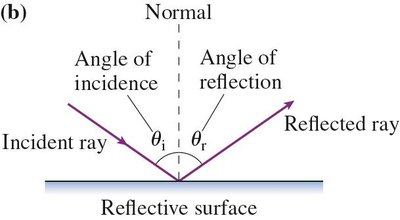
Reflection is the process by which light bounces off a surface. The law of reflection governs how light rays interact with reflective surfaces, such as mirrors.
Law of Reflection: The angle of incidence () equals the angle of reflection (), and both rays lie in the same plane perpendicular to the surface.
Angles are measured from the normal: The normal is an imaginary line perpendicular to the surface at the point of incidence.
Ray Model: A single light ray can represent a bundle of parallel rays for analysis.
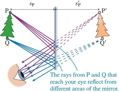
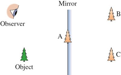
Plane Mirrors: Rays from each point on an object spread out and reflect from different areas of the mirror, allowing observers to see images from various perspectives.
Example: Locating the Image in a Plane Mirror
Images appear to be located behind the mirror at the same distance as the object is in front.
Only rays that enter the observer's eye contribute to the perceived image.
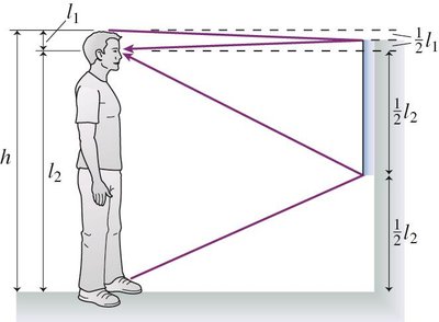
Example: Minimum Mirror Height
To see your full image, the shortest mirror required is half your height ().
This result is independent of your distance from the mirror.
Ray tracing shows that rays from the top and bottom of your body reflect into your eyes if the mirror is at least half your height.


Refraction
Refraction is the bending of light as it passes from one medium to another, caused by a change in the speed of light.
Angle of Incidence: The angle between the incident ray and the normal.
Angle of Refraction: The angle between the refracted ray and the normal.
Snell's Law: Describes the relationship between the angles and the indices of refraction of the two media:
Index of Refraction (n): A measure of how much the speed of light is reduced in a medium.
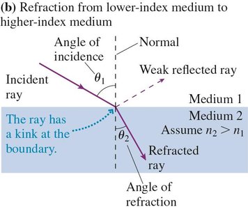
Table: Indices of Refraction
Medium | n |
|---|---|
Vacuum | 1 (exactly) |
Air (accepted) | 1.00 |
Water | 1.33 |
Oil | 1.46 |
Glass (typical) | 1.50 |
Polystyrene plastic | 1.59 |
Cubic zirconia | 2.18 |
Diamond | 2.42 |
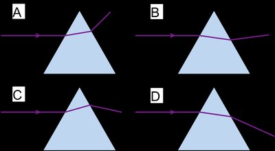
Ray Diagrams and Snell's Law
Draw the incident and refracted rays, and the normal at the boundary.
The ray bends toward the normal when entering a medium with higher n.
Use Snell's law to calculate unknown angles or indices.
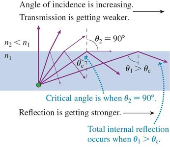
Total Internal Reflection
Total internal reflection (TIR) occurs when light attempts to move from a medium with higher n to lower n at an angle greater than the critical angle (), resulting in all light being reflected.
Critical Angle (): The angle of incidence for which the angle of refraction is 90°.
Condition for TIR: and .
No TIR: If , TIR does not occur.
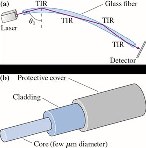
Applications: Fiber Optics
Light is guided through optical fibers by repeated TIR at the core-cladding boundary.
Used in telecommunications and medical endoscopes.
Thin Lenses: Ray Tracing
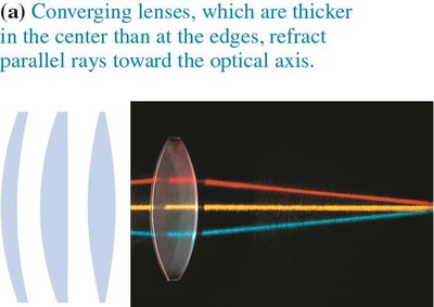
Lenses refract light to form images. There are two main types: converging (thicker in the center) and diverging (thinner in the center).
Converging Lens: Refracts rays toward the optical axis.
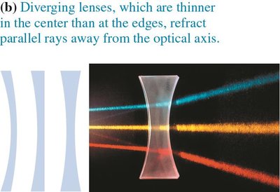
Diverging Lens: Refracts rays away from the optical axis.
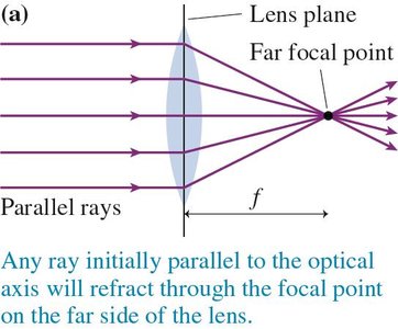
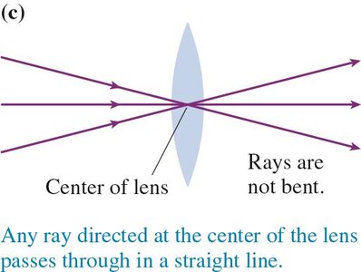
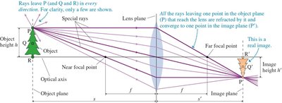
Ray Tracing for Converging Lenses
Rays parallel to the optical axis refract through the far focal point.
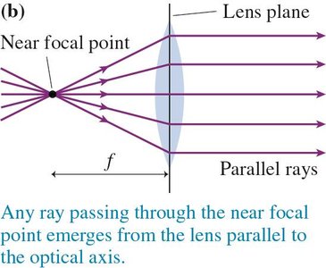
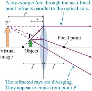
Rays passing through the near focal point emerge parallel to the optical axis.
Rays directed at the center pass straight through.
Real Images
Formed when refracted rays converge at a point.
Can be projected onto a screen.
Magnification
Magnification () is the ratio of image height to object height.
Positive means upright image; negative $m$ means inverted image.
Virtual Images
Formed when refracted rays diverge, appearing to originate from a point.
Cannot be projected onto a screen; seen by looking through the lens.
Always upright for diverging lenses.
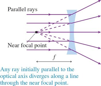
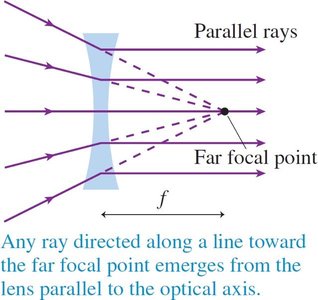
Diverging Lenses
Thinner at the center than at the edges.
Always produce virtual, upright, and smaller images.
Ray tracing involves:
Ray parallel to axis diverges along a line through near focal point.
Ray toward far focal point emerges parallel to axis.
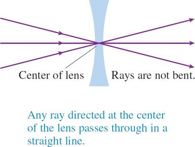
Ray through center passes straight.
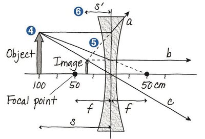
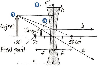
Example: Image Location for Diverging Lens
For a diverging lens with cm and object distance cm, the image forms at cm.
Magnification: (image is upright and one-third the size of the object).
Spherical Mirrors
Spherical mirrors can be converging (concave) or diverging (convex).
Converging Mirrors: Reflect rays to converge at a focal point, forming real or virtual images depending on object position.
Diverging Mirrors: Reflect rays outward, forming virtual, upright, and smaller images.
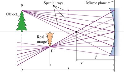

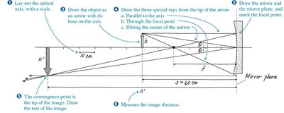
Example: Converging Mirror
Object height: 3.0 cm, object distance: 60 cm, focal length: 40 cm.
Image position: cm, magnification: (image is inverted and twice the object height).
Example: Diverging Mirror
Convex mirrors are used for wide field of view, such as passenger-side car mirrors.
Images are smaller and appear more distant than they actually are.
The Thin-Lens Equation
The thin-lens equation relates object distance (), image distance (), and focal length ():
Sign conventions:
Converging lens/mirror: is positive.
Diverging lens/mirror: is negative.
Real images (inverted): is positive.
Virtual images (upright): is negative.
Example: Magnifying Lens
Magnification: (upright, virtual image).
Object distance: 2.0 cm, image distance: -8.0 cm.
Focal length: cm.
Summary Table: Types of Images
Optical Element | Image Type | Orientation | Size |
|---|---|---|---|
Converging Lens | Real or Virtual | Inverted or Upright | Larger or Smaller |
Diverging Lens | Virtual | Upright | Smaller |
Converging Mirror | Real or Virtual | Inverted or Upright | Larger or Smaller |
Diverging Mirror | Virtual | Upright | Smaller |
Plane Mirror | Virtual | Upright | Same size |
