 Back
BackRay Optics: Reflection, Refraction, Mirrors, and Lenses
Study Guide - Smart Notes
 Tailored notes based on your materials, expanded with key definitions, examples, and context.
Ray Optics and the Ray Model of Light
Introduction to Ray Optics
Ray optics, also known as geometrical optics, is a branch of physics that describes the propagation of light as rays. This model is valid when the wavelength of light is much smaller than the obstacles or slits it encounters, making the direction of motion the key property.
Light ray: A line indicating the direction of travel of a wave, perpendicular to the wavefronts.
Ray optics: Focuses on tracing rays as light is reflected or refracted.
Reflection and Refraction
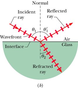
Reflection and Refraction at Boundaries
When light encounters a boundary between two media, it can be reflected or transmitted (refracted).
Reflection: The bouncing of light off a surface.
Refraction: The bending of light as it passes from one medium to another.
Laws Governing Reflection and Refraction
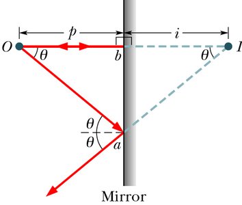
Law of Reflection: The angle of reflection () equals the angle of incidence (), and both rays lie in the plane of incidence.
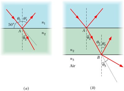
Law of Refraction (Snell's Law): The angle of refraction () is related to the angle of incidence () by: where and are the refractive indices of the two media.
Refractive Index: A property of the medium, dependent on wavelength.
Light bends toward the normal when entering a more optically dense medium (higher ), and away from the normal when entering a less dense medium.
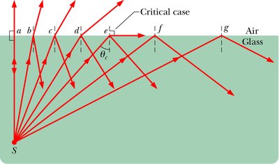
Total Internal Reflection
When light travels from a medium with higher refractive index to one with lower index, there is a critical angle () above which all light is reflected and none is refracted.
Critical angle:
Total internal reflection: Occurs when the angle of incidence exceeds .
Plane Mirrors
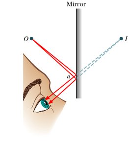
Image Formation in Plane Mirrors
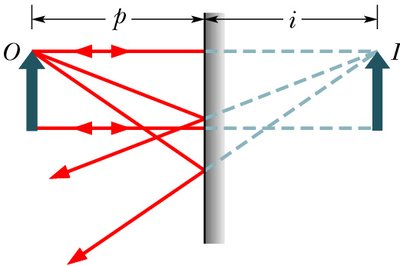
A plane mirror creates a virtual image that appears as far behind the mirror as the object is in front.
Virtual image: No rays actually leave the image point; it is perceived by extending reflected rays backward.
Object distance (): Perpendicular distance from object to mirror.
Image distance (): Perpendicular distance from image to mirror; for virtual images, is negative.
For a plane mirror:
Spherical Mirrors
Concave and Convex Mirrors
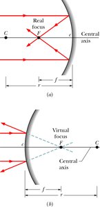
Spherical mirrors are sections of a sphere and can be concave (curved inward) or convex (curved outward).
Concave mirror: Reflecting surface is caved in; focal point is in front of the mirror.
Convex mirror: Reflecting surface is flexed out; focal point is behind the mirror.
Focal length (): Distance from mirror to focal point; where is the radius of curvature.
Focal length is positive for concave mirrors and negative for convex mirrors.
Ray Diagrams for Spherical Mirrors
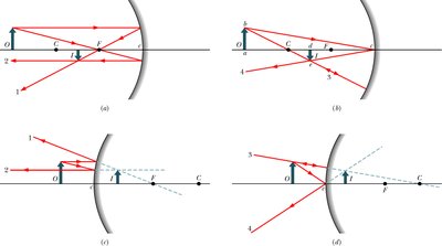
The image of an extended source can be located using ray diagrams with special rays:
Ray parallel to central axis reflects through focal point.
Ray passing through focal point reflects parallel to central axis.
Ray passing through center of curvature returns along itself.
Ray reflecting at intersection with central axis is reflected symmetrically.
Mirror Equation and Magnification
Mirror equation:
Magnification ():
If is negative, the image is inverted; if positive, upright.
Thin Lenses
Types of Lenses and Image Formation
Lenses consist of two refracting surfaces.
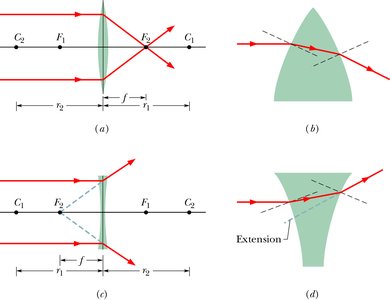
Converging lens: Causes parallel rays to converge at a focal point.
Diverging lens: Causes parallel rays to diverge; extensions pass through a focal point.
Thin lenses: Thickness is small compared to object and image distances and radii of curvature.
Lens Maker's Equation
For a lens of refractive index in air:
is positive for convex surfaces facing the object, negative for concave.
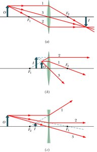
Ray Diagrams for Lenses
To locate the image of an off-axis point, use any two of three special rays:
Ray parallel to central axis passes through focal point .
Ray passing through focal point emerges parallel to central axis.
Ray directed toward center of lens emerges with no change in direction.
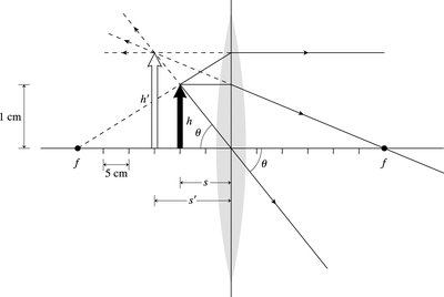
Lens Equation and Magnification
Lens equation:
Magnification:
Real images form on the side opposite the object; virtual images form on the same side as the object.
Summary Tables
Mirror Types and Image Properties
Mirror Type | Object Location | Image Location | Type | Orientation | Sign of f | Sign of m |
|---|---|---|---|---|---|---|
Plane | Anywhere | Opposite | Virtual | Upright | --- | + |
Concave (inside F) | Inside F | Opposite | Virtual | Upright | + | + |
Concave (outside F) | Outside F | Same | Real | Inverted | + | - |
Convex | Anywhere | Opposite | Virtual | Upright | - | + |
Lens Types and Image Properties
Lens Type | Object Location | Image Location | Type | Orientation | Sign of f | Sign of m |
|---|---|---|---|---|---|---|
Converging (inside F) | Inside F | Same | Virtual | Upright | + | + |
Converging (outside F) | Outside F | Opposite | Real | Inverted | + | - |
Diverging | Anywhere | Same | Virtual | Upright | - | + |
Key Equations
Snell's Law:
Critical Angle:
Mirror Equation:
Lens Equation:
Lens Maker's Equation:
Magnification:
Examples and Applications
Plane mirrors create virtual, upright images at equal distances behind the mirror.
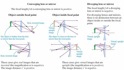
Concave mirrors can form real, inverted images or virtual, upright images depending on object location.
Convex mirrors always form virtual, upright images.
Converging lenses can form real, inverted images or virtual, upright images.
Diverging lenses always form virtual, upright images.
Additional info:
All equations are provided in LaTeX format for clarity and academic rigor.
Tables summarize the properties of mirrors and lenses for quick reference.
