Back
BackReflection and Refraction of Light: Mirrors, Lenses, and Optical Instruments
Study Guide - Smart Notes
 Tailored notes based on your materials, expanded with key definitions, examples, and context.
Reflection of Light: Mirrors
Formation of Images by a Plane Mirror
When an object is placed in front of a plane (flat) mirror, the mirror forms an image with specific properties due to the law of reflection. The image appears to be located behind the mirror at the same distance as the object is in front of it.
Upright Image: The image is upright, maintaining the same orientation as the object.
Same Size: The image is the same size as the object.
Equal Distance: The image appears as far behind the mirror as the object is in front of it ().
Left-Right Reversal: The image is reversed left-to-right. For example, your right hand appears as the left hand in the image.
Virtual Image: The image is virtual, meaning light rays do not actually pass through the image location; they only appear to do so when extended backward.
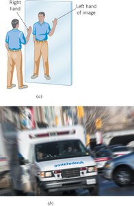
Example: Emergency vehicles often have reversed lettering on the front so that drivers see the word correctly in their rearview mirrors.
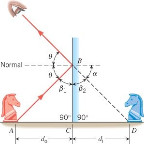
Geometric Construction of Plane Mirror Images
The formation of images by a plane mirror can be analyzed using ray diagrams and geometry. The object distance () and image distance () are equal, as shown by similar triangles in the diagram.
Law of Reflection: The angle of incidence equals the angle of reflection ().
Virtual Image Location: The image appears behind the mirror at a distance equal to the object’s distance in front of the mirror.
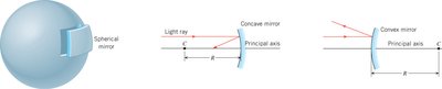
Spherical Mirrors
Types and Properties of Spherical Mirrors
Spherical mirrors are segments of a sphere and can be either concave (inwardly curved) or convex (outwardly curved). The principal axis passes through the center of curvature (C) and the mirror's midpoint. The law of reflection applies to both types.
Concave Mirror: The inside surface is polished; it converges parallel rays to a focal point (F).
Convex Mirror: The outside surface is polished; it diverges parallel rays, which appear to originate from a focal point behind the mirror.
Radius of Curvature (R): The radius of the sphere from which the mirror is taken.
Focal Length (f): The distance from the mirror to the focal point. For spherical mirrors, .
Ray Tracing and Image Formation by Concave Mirrors
Ray tracing is used to determine the location and nature of images formed by concave mirrors. The image characteristics depend on the object's position relative to the focal point (F) and center of curvature (C).
Object Beyond C: Image is real, inverted, and reduced.
Object Between F and C: Image is real, inverted, and magnified.
Object Between Mirror and F: Image is virtual, upright, and magnified.
Principle of Reversibility: Light rays retrace their path if their direction is reversed.
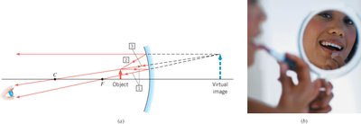
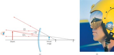
Ray Tracing and Image Formation by Convex Mirrors
Convex mirrors always form virtual, upright, and reduced images regardless of the object's position.
Ray 1: Parallel to principal axis, appears to originate from focal point.
Ray 2: Directed toward focal point, emerges parallel to principal axis.
Ray 3: Directed toward center of curvature, reflects back on itself.
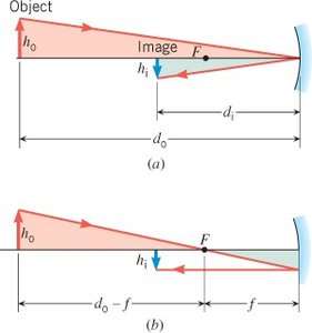
The Mirror Equation and Magnification
The mirror equation relates the object distance (), image distance (), and focal length () for both concave and convex mirrors. Magnification () describes the ratio of image height to object height.
Mirror Equation:
Magnification Equation:
Sign Conventions: For concave mirrors, is positive; for convex mirrors, $f$ is negative. Real images have positive ; virtual images have negative $d_i$.
Refraction of Light: Lenses and Optical Instruments
Index of Refraction
The index of refraction () quantifies how much the speed of light is reduced in a material compared to vacuum. It is defined as:
Definition: , where is the speed of light in vacuum and is the speed in the material.
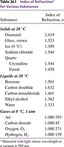
Typical Values: Air: ~1.00, Water: 1.33, Glass: 1.5–1.7, Diamond: 2.42.
Substance | Index of Refraction, n |
|---|---|
Diamond | 2.419 |
Glass, crown | 1.523 |
Ice (0°C) | 1.309 |
Water | 1.333 |
Air (0°C, 1 atm) | 1.000293 |
Oxygen | 1.000271 |
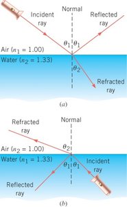
Snell’s Law and the Refraction of Light
When light passes from one medium to another, it changes direction—a phenomenon called refraction. Snell’s Law relates the angles and indices of refraction of the two media:
Snell’s Law:
Angle of Incidence (): Angle between incident ray and normal.
Angle of Refraction (): Angle between refracted ray and normal.

Example: Determining the Angle of Refraction
Given a light ray striking an air/water interface at 46°, Snell’s Law can be used to find the angle of refraction for both directions (air to water and water to air).
Air to Water: , ,
Water to Air: , ,
Displacement of Light by a Slab
When light passes through a parallel-sided slab (like a glass pane), the emergent ray is parallel to the incident ray but displaced sideways. The angles of incidence and emergence are equal ().
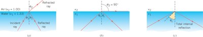
Total Internal Reflection
Total internal reflection occurs when light attempts to move from a medium with higher index of refraction to one with lower index at an angle greater than the critical angle (). Beyond this angle, all light is reflected back into the original medium.
Critical Angle: , where .
Applications: Used in prisms, binoculars, and optical fibers.
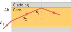
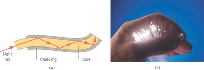
Total Internal Reflection in Optical Fibers
Optical fibers use total internal reflection to transmit light over long distances with minimal loss. The core has a higher index of refraction than the cladding, ensuring light is reflected internally.
Core-Cladding Interface: Light is confined within the core by total internal reflection.
Telecommunications: Optical fibers are essential for high-speed data transmission.
Example: Critical Angle in Optical Fibers
For a fiber with a flint glass core () and crown glass cladding (), the critical angle and the maximum angle of incidence for total internal reflection can be calculated using Snell’s Law and geometry.
Critical Angle:
Maximum Entry Angle: Determined by tracing the path from air into the core and then to the cladding.