 Back
BackReflection and Refraction of Light: Mirrors and Lenses
Study Guide - Smart Notes
 Tailored notes based on your materials, expanded with key definitions, examples, and context.
Reflection & Refraction of Light
Law of Reflection
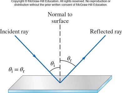
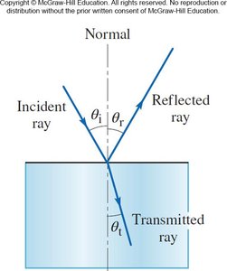
The law of reflection governs how light behaves when it encounters a reflective surface. The angle of incidence (\( \theta_i \)) is the angle between the incident ray and the normal (a line perpendicular to the surface), while the angle of reflection (\( \theta_r \)) is the angle between the reflected ray and the normal.
Law of Reflection: The angle of incidence equals the angle of reflection: \( \theta_i = \theta_r \).
Both the incident ray and the reflected ray lie in the same plane as the normal.
Types of Reflection
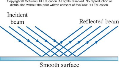
Specular Reflection: Occurs on smooth surfaces where all incident rays reflect at the same angle, producing clear images. This is important in optical instruments.
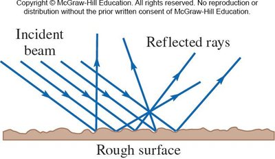
Diffuse Reflection: Occurs on rough, irregular surfaces where reflected rays scatter in many directions. This type of reflection allows us to see most objects around us.
Refraction of Light
Refraction and Its Properties
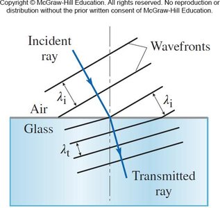
Refraction is the bending of light as it passes from one transparent medium to another. This occurs because the speed of light changes in different media, altering the direction of the light ray. The frequency of light remains constant, but the wavelength and apparent speed change.
Index of Refraction
The index of refraction (\( n \)) quantifies how much light slows down in a material compared to its speed in a vacuum (\( c \)).
\( n = \frac{c}{v} \), where \( v \) is the speed of light in the material.
The higher the index, the more the light ray bends.
Substance | Index of Refraction (n) | Light Speed |
|---|---|---|
Air | ~1 | ~c |
Water | 1.333 | 0.75c |
Glass | 1.5 | 0.67c |
Diamond | 2.4 | 0.42c |
Bose-Einstein condensate | 18,000,000 | 38 mph |
Snell's Law (Law of Refraction)
Snell's Law describes how light bends when passing between two media with different indices of refraction:
\( n_i \sin \theta_i = n_t \sin \theta_t \)
\( n_i \): Index of refraction of the incident medium
\( \theta_i \): Angle of incidence
\( n_t \): Index of refraction of the transmitted medium
\( \theta_t \): Angle of transmission (refraction)
The incident ray, transmitted ray, and normal all lie in the same plane.
Formation of Images
Real and Virtual Images
Images formed by mirrors and lenses can be classified as real or virtual:
Real Image: Light rays actually converge at the image location. The image can be projected onto a screen.
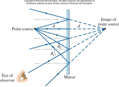
Virtual Image: Light rays only appear to diverge from the image location. The image cannot be projected onto a screen.
Mirrors
Types of Mirrors
Mirrors form images by reflection. There are three main types:
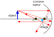
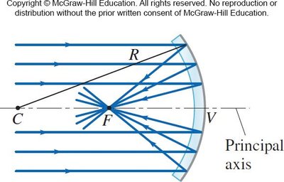
Concave (Converging) Mirrors: Curved inward, causing parallel rays to converge at a focal point.
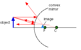
Convex (Diverging) Mirrors: Curved outward, causing parallel rays to diverge as if from a focal point behind the mirror.
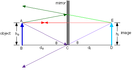
Plane Mirrors: Flat mirrors that produce images with the same size as the object and at the same distance behind the mirror as the object is in front.
Principal Rays for Spherical Mirrors
Ray diagrams help locate images formed by spherical mirrors. For concave mirrors:
Ray 1: Parallel to the principal axis, reflects through the focal point.
Ray 2: Passes through the center of curvature, reflects back on itself.
Ray 3: Passes through the focal point, reflects parallel to the principal axis.
Ray 4: Strikes the vertex, reflects at an equal angle to the axis.
For convex mirrors:
Ray 1: Parallel to the principal axis, reflects as if from the focal point.
Ray 2: Directed toward the center of curvature, reflects back on itself.
Ray 3: Directed toward the focal point, reflects parallel to the principal axis.
Ray 4: Strikes the vertex, reflects at an equal angle to the axis.
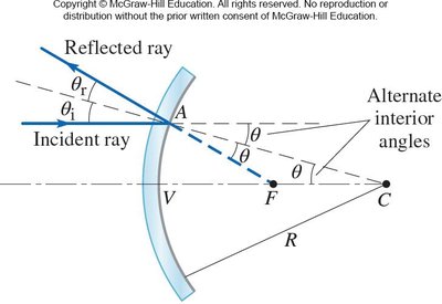
Focal Length and Mirror Equation
The focal length (\( f \)) of a spherical mirror is half the radius of curvature (\( R \)):
\( f = \frac{1}{2} R \)
The mirror equation relates object distance (\( d_o \)), image distance (\( d_i \)), and focal length (\( f \)):
\( \frac{1}{d_o} + \frac{1}{d_i} = \frac{1}{f} \)
Sign Conventions for Mirrors
Quantity | Positive (+) | Negative (−) |
|---|---|---|
Object distance (\( d_o \)) | Real object | Never |
Image distance (\( d_i \)) | Real image | Virtual image |
Focal length (\( f \)) | Converging (concave) | Diverging (convex) |
Real images are always inverted; virtual images are always upright.
Plane Mirrors
The image is the same size as the object.
The image distance equals the object distance from the mirror.
Lenses
Lenses and Refraction
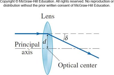
Lenses form images by refraction. A spherical lens has two surfaces, each a section of a sphere. The principal axis passes through the centers of curvature of both surfaces, and the optical center is the point through which rays pass without deviation.
Types of Lenses
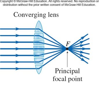
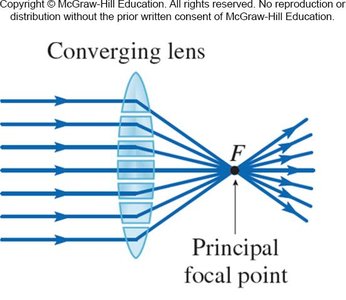
Converging (Convex) Lens: Bends light rays inward toward the principal axis, causing them to converge at a focal point.
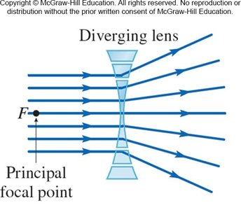
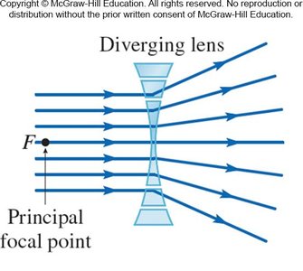
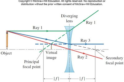
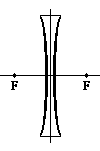
Diverging (Concave) Lens: Bends light rays outward, causing them to diverge as if from a focal point.
Paraxial Rays
For thin lenses, we consider paraxial rays—rays close to the principal axis and at small angles of incidence. The deviation angle (\( \delta \)) is proportional to the distance from the center.
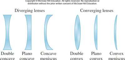
Common Shapes of Thin Lenses
Diverging Lenses | Converging Lenses |
|---|---|
Double concave, Plano concave, Concave meniscus | Double convex, Plano convex, Convex meniscus |
Focal Points of Lenses
Every lens has two focal points (principal and secondary), one on each side.
The focal length depends on the radii of curvature and the indices of refraction of the lens and surrounding medium.
For a diverging lens, parallel rays appear to diverge from the principal focal point before the lens.
For a converging lens, parallel rays converge to the principal focal point past the lens.
Principal Rays for Lenses
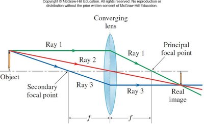
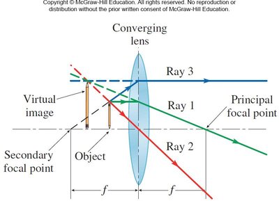
For a converging lens:
Ray 1: Parallel to the principal axis, passes through the principal focal point.
Ray 2: Passes through the optical center, continues straight.
Ray 3: Emerges parallel to the principal axis, appears to come from the secondary focal point.
The Thin Lens Equation
The thin lens equation relates object distance (\( d_o \)), image distance (\( d_i \)), and focal length (\( f \)):
\( \frac{1}{d_o} + \frac{1}{d_i} = \frac{1}{f} \)
Worked Examples
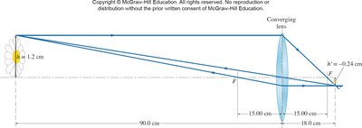
Example 1 (Converging Lens): A wild daisy is 90.0 cm from a camera’s zoom lens (focal length 15.0 cm). Find the image distance.
Given: \( d_o = 90.0 \) cm, \( f = +15.0 \) cm
\( \frac{1}{d_o} + \frac{1}{d_i} = \frac{1}{f} \)
\( \frac{1}{90.0} + \frac{1}{d_i} = \frac{1}{15.0} \)
\( d_i = 18.0 \) cm
Example 2 (Diverging Lens): An object is 50.0 cm from a diverging lens, and the image is formed 15.0 cm from the lens. Find the focal length.
Given: \( d_o = 50.0 \) cm, \( d_i = -15.0 \) cm
\( \frac{1}{50.0} + \frac{1}{-15.0} = \frac{1}{f} \)
\( f = -21.4 \) cm (negative sign indicates diverging lens)
Additional info: The sign conventions for lenses are similar to those for mirrors. For converging lenses, the focal length is positive; for diverging lenses, it is negative. Real images are formed on the opposite side of the lens from the object, while virtual images are on the same side as the object.
