 Back
BackStep-by-Step Guidance for Circuits and Resistance Problems (Chapter 23)
Study Guide - Smart Notes
 Tailored notes based on your materials, expanded with key definitions, examples, and context.
Q1. Ranking the Brightness of Bulbs in a Circuit (Figure Q23.18)
Background
Topic: Series and Parallel Circuits, Power Dissipation
This question tests your understanding of how current and voltage are distributed in series and parallel circuits, and how these affect the brightness (power output) of identical bulbs.
Key Terms and Formulas:
Power dissipated by a resistor (bulb):
Series circuit: Same current flows through all components.
Parallel circuit: Same voltage across each branch; current splits between branches.
Step-by-Step Guidance
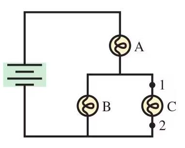
Identify which bulbs are in series and which are in parallel. Bulb A is in series with the battery, while bulbs B and C are in parallel with each other and together in series with A.
Recall that the total current from the battery passes through bulb A first, then splits between bulbs B and C.
Since the bulbs are identical, the current splits equally between B and C. Use the power formula to compare brightness: for each bulb.
Rank the bulbs by brightness based on the current through each and explain your reasoning.
Try solving on your own before revealing the answer!
Q2. Effect of Connecting a Wire Between Points 1 and 2 (Figure Q23.18)
Background
Topic: Short Circuits, Parallel Paths
This part tests your understanding of what happens when a low-resistance path (wire) is added in parallel with a circuit element.
Key Terms and Formulas:
Short circuit: A path with negligible resistance, causing current to bypass other components.
Ohm's Law:
Step-by-Step Guidance
Consider what happens to the current when a wire (zero resistance) is connected between points 1 and 2, bypassing bulb C.
Analyze the effect on bulb C: Does any current flow through it, or does it go out?
Analyze the effect on bulb B: Is there any voltage across it, or does it go out as well?
Consider the effect on bulb A: With the parallel section replaced by a wire, what happens to the total resistance and the current through A?
Try solving on your own before revealing the answer!
Q3. Drawing a Circuit from a Potential Change Graph (Figure P23.9)
Background
Topic: Series Circuits, Potential Changes
This question tests your ability to interpret a graph of potential changes around a circuit and translate it into a circuit diagram.
Key Terms and Formulas:
Ohm's Law:
Series circuit: The sum of voltage drops across resistors equals the battery voltage.
Step-by-Step Guidance
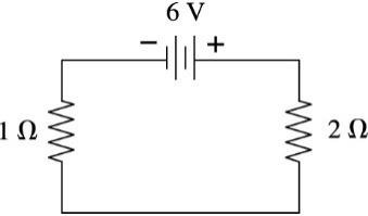
Associate each change in potential (gain or loss) with a circuit element: battery (gain), resistor (loss).
Use the given current (2.0 A) and the voltage drops (2 V and 4 V) to determine the resistance values using .
Draw the circuit diagram with the battery and two resistors in series, labeling their values.
Check that the total voltage drop equals the battery voltage, confirming your diagram.
Try solving on your own before revealing the answer!
Q4. Equivalent Resistance Between Points a and b (Figure P23.19)
Background
Topic: Series and Parallel Resistor Combinations
This question tests your ability to reduce a complex resistor network to a single equivalent resistance using series and parallel rules.
Key Terms and Formulas:
Series combination:
Parallel combination:
Step-by-Step Guidance
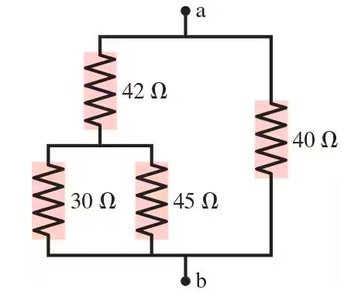
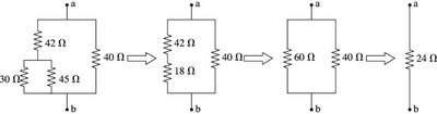
Identify which resistors are in parallel and which are in series. Start by combining the 30 Ω and 45 Ω resistors in parallel.
Combine the result with the 42 Ω resistor in series.
Combine the result with the 40 Ω resistor in parallel to find the total equivalent resistance between a and b.
Write out the equations for each step, but stop before the final calculation.
Try solving on your own before revealing the answer!
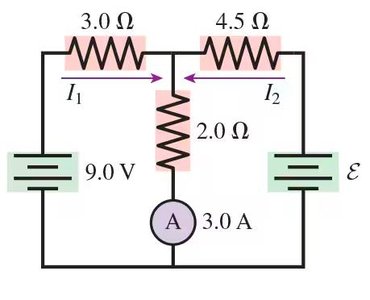
Q5. Currents and EMF in a Multi-Loop Circuit (Figure P23.26)
Background
Topic: Kirchhoff's Rules (Loop and Junction Laws)
This question tests your ability to apply Kirchhoff’s laws to solve for unknown currents and EMF in a multi-loop circuit.
Key Terms and Formulas:
Kirchhoff’s Junction Law:
Kirchhoff’s Loop Law: around any closed loop
Ohm’s Law:
Step-by-Step Guidance
Apply the junction law at the node where the currents split: .
Apply the loop law to the left loop to solve for in terms of known values.
Use the result to solve for using the junction law.
Apply the loop law to the right loop to solve for the unknown EMF , but stop before the final calculation.
Try solving on your own before revealing the answer!
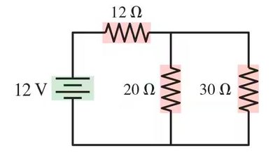
Q6. Currents and Voltages in a Parallel-Resistor Circuit (Figure P23.27)
Background
Topic: Series and Parallel Circuits, Ohm’s Law, Kirchhoff’s Laws
This question tests your ability to analyze a circuit with both series and parallel resistors, finding the current through and voltage across each resistor.
Key Terms and Formulas:
Ohm’s Law:
Series combination:
Parallel combination:
Kirchhoff’s Laws: Use for checking current splits and voltage drops.
Step-by-Step Guidance
Find the equivalent resistance of the parallel section (20 Ω and 30 Ω in parallel), then add the series 12 Ω resistor.
Calculate the total current supplied by the battery using .
Determine the current through the 12 Ω resistor (all current passes through it).
Find the voltage drop across the 12 Ω resistor, then use the remaining voltage to find the current through each parallel resistor, but stop before the final calculation.
Try solving on your own before revealing the answer!
